Green Pin Power Sling® Shackle BN
High load capacity, grade 8 shackle with safety bolt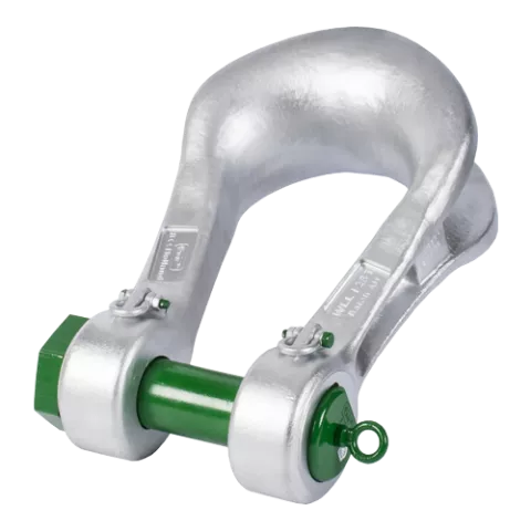
- Highlights
- Saves up to 20% on cost of wire rope
- Improves safety thanks to multiple handling points and RFID-tracking
- Unique Green Pin® design (patent pending)
- Best choice for heavy lifting projects
- Superior stock availability of 99%
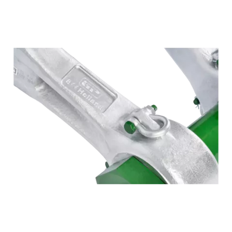
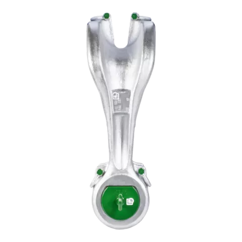
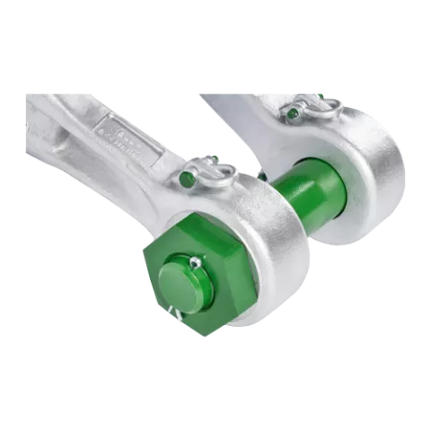
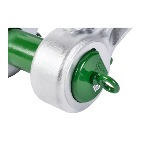
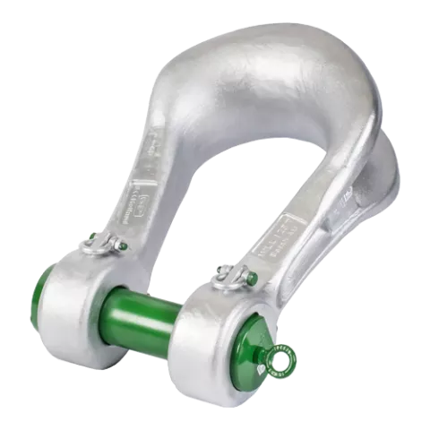
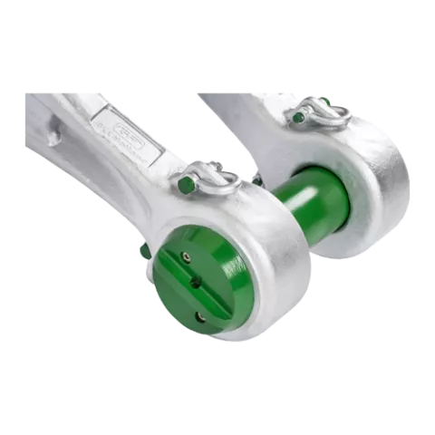
The Green Pin Power Sling® Shackle BN is specially developed for heavy lifting. It is the top product in the Green Pin® shackle assortment and the wider lifting industry. The Green Pin Power Sling® Shackle BN has a bending efficiency of 85%. Its shackle crown is the widest in the industry (10% more than shackles of the previous generation) and has an optimal D/d ratio. Furthermore, the areas of the Power Sling® shackle that endure the highest stress have been reinforced. As a result, the Power Sling® lets you save up to 20% on synthetic- and wire rope costs. The long-term performance of the Power Sling® has been scrutinized with tensile- and fatigue testing, subjecting it to more than 40.000 cycles (the API norm specifies 20.000 cycles). Each shackle is proofload tested to twice the working load limit. Ductility of the steel has also been checked at temperatures as low as minus 40 °Celsius degree (-40 °F). Safety and efficiency for riggers are other key benefits of the Power Sling®. The Power Sling® is equipped with six handling points to the body and several more on the pin (larger sizes have more handling points than smaller sizes). Many such handling points are smaller shackles that are attached to the main shackle. Lifting the Power Sling® into place becomes a much safer and easier activity as a result. The Power Sling® can be supplied with a variety of certificates. The Green Pin Power Sling® Shackle BN is available in a range with a working load limit from 125 to 1550T. More information (product video, brochure) can be found on the website http://greenpin.com/power.
More-
ProductcodeP-6043
-
Materialbow and pin alloy steel, Grade 8, quenched and tempered
-
Safety factorMBL equals 5 x WLL
-
Finishshackle bow painted silver, pin painted green
-
Temp. range-40°C up to +200°C
-
Certification
- 2.1
- 2.2
- 3.1
- MTCb
- LROS
- MPIb
- USb
- DNVGL-ST-0378
- CE
- DNV-GL-ST-0377
| Article code |
working load limit
(ton)
|
working load limit
(ton)
|
Weight shackle pin
(kg)
|
Weight shackle pin
(lb)
|
diameter pin
(mm)
B
|
diameter pin (inch)
B
|
diameter eye
(mm)
C
|
diameter eye (inch)
C
|
width eye (inch)
D
|
width eye
(mm)
D
|
width inside
(mm)
E
|
width inside (inch)
E
|
length inside (inch)
F
|
length inside
(mm)
F
|
width bow (inch)
G
|
width bow
(mm)
G
|
length (inch)
H
|
length
(mm)
H
|
length bolt (inch)
I
|
length bolt
(mm)
I
|
width (inch)
J
|
width
(mm)
J
|
thickness nut (inch)
K
|
thickness nut
(mm)
K
|
bearing surface (inch)
L
|
bearing surface
(mm)
L
|
Net weight (KG) | Net weight (LBS) | |
|---|---|---|---|---|---|---|---|---|---|---|---|---|---|---|---|---|---|---|---|---|---|---|---|---|---|---|---|---|---|
| SLPGP0125 | 125 | 16,83 | 81 | 165 | 89 | 134 | 365 | 220 | 632 | 382 | 370 | 36 | 205 | 95 | |||||||||||||||
| SLPGP0125 | 125 | 37,1 | 3 3/16 | 6 1/2 | 3 1/2 | 5 9/32 | 14 3/8 | 8 21/32 | 24 7/8 | 15 1/32 | 14 9/16 | 1 13/32 | 8 1/16 | 209 | |||||||||||||||
| SLPGP0150 | 150 | 25,83 | 95 | 182 | 90 | 144 | 390 | 250 | 703 | 408 | 420 | 42 | 248 | 134 | |||||||||||||||
| SLPGP0150 | 150 | 56,95 | 3 3/4 | 7 5/32 | 3 17/32 | 5 21/32 | 15 11/32 | 9 27/32 | 27 11/16 | 16 1/16 | 16 17/32 | 1 21/32 | 9 3/4 | 295 | |||||||||||||||
| SLPGP0200 | 200 | 35,1 | 105 | 204 | 100 | 154 | 480 | 276 | 838 | 446 | 474 | 47 | 290 | 195 | |||||||||||||||
| SLPGP0200 | 200 | 77,38 | 4 1/8 | 8 1/32 | 3 15/16 | 6 1/16 | 18 29/32 | 10 7/8 | 33 | 17 9/16 | 18 21/32 | 1 27/32 | 11 13/32 | 430 | |||||||||||||||
| SLPGP0250 | 250 | 54,2 | 120 | 238 | 114 | 174 | 540 | 300 | 938 | 503 | 513 | 60 | 314 | 271 | |||||||||||||||
| SLPGP0250 | 250 | 119,49 | 4 23/32 | 9 3/8 | 4 1/2 | 6 27/32 | 21 1/4 | 11 13/16 | 36 15/16 | 19 13/16 | 20 3/16 | 2 3/8 | 12 3/8 | 598 | |||||||||||||||
| SLPGP0300 | 300 | 71,3 | 134 | 260 | 125 | 189 | 600 | 350 | 1032 | 550 | 604 | 60 | 345 | 368 | |||||||||||||||
| SLPGP0300 | 300 | 157,19 | 5 9/32 | 10 1/4 | 4 29/32 | 7 7/16 | 23 5/8 | 13 25/32 | 40 5/8 | 21 21/32 | 23 25/32 | 2 3/8 | 13 19/32 | 811 | |||||||||||||||
| SLPGP0400 | 400 | 122,2 | 160 | 305 | 144 | 224 | 620 | 370 | 1123 | 645 | 653 | 80 | 392 | 563 | |||||||||||||||
| SLPGP0400 | 400 | 269,4 | 6 5/16 | 12 | 5 21/32 | 8 13/16 | 24 13/32 | 14 9/16 | 44 7/32 | 25 13/32 | 25 23/32 | 3 5/32 | 15 7/16 | 1241 | |||||||||||||||
| SLPGP0500 | 500 | 163,6 | 180 | 340 | 157 | 255 | 680 | 450 | 1239 | 714 | 763 | 85 | 440 | 786 | |||||||||||||||
| SLPGP0500 | 500 | 360,68 | 7 3/32 | 13 3/8 | 6 3/16 | 10 1/32 | 26 25/32 | 17 23/32 | 48 25/32 | 28 1/8 | 30 1/32 | 3 11/32 | 17 5/16 | 1733 | |||||||||||||||
| SLPGP0600 | 600 | 220,6 | 200 | 365 | 175 | 280 | 741 | 490 | 1354 | 788 | 818 | 90 | 475 | 1009 | |||||||||||||||
| SLPGP0600 | 600 | 486,34 | 7 7/8 | 14 3/8 | 6 7/8 | 11 1/32 | 29 3/16 | 19 9/32 | 53 5/16 | 31 1/32 | 32 7/32 | 3 17/32 | 18 11/16 | 2225 | |||||||||||||||
| SLPGP0700 | 700 | 288,7 | 215 | 405 | 195 | 320 | 751 | 540 | 1415 | 879 | 893 | 100 | 512 | 1288 | |||||||||||||||
| SLPGP0700 | 700 | 636,47 | 8 15/32 | 15 15/16 | 7 11/16 | 12 19/32 | 29 9/16 | 21 1/4 | 55 23/32 | 34 19/32 | 35 5/32 | 3 15/16 | 20 5/32 | 2840 | |||||||||||||||
| SLPGP0800 | 800 | 353,6 | 230 | 430 | 205 | 347 | 851 | 554 | 1547 | 945 | 917 | 108 | 536 | 1503 | |||||||||||||||
| SLPGP0800 | 800 | 779,55 | 9 1/16 | 16 15/16 | 8 1/16 | 13 21/32 | 33 1/2 | 21 13/16 | 60 29/32 | 37 7/32 | 36 3/32 | 4 1/4 | 21 3/32 | 3314 | |||||||||||||||
| SLPGP0900 | 900 | 472,7 | 255 | 476 | 220 | 373 | 852 | 580 | 1599 | 1013 | 972 | 120 | 560 | 1849 | |||||||||||||||
| SLPGP0900 | 900 | 1042,13 | 10 1/32 | 18 3/4 | 8 21/32 | 14 11/16 | 33 17/32 | 22 27/32 | 62 15/16 | 39 7/8 | 38 9/32 | 4 23/32 | 22 1/16 | 4077 | |||||||||||||||
| SLPGP1000 | 1000 | 571 | 270 | 500 | 237 | 405 | 851 | 614 | 1643 | 1085 | 1022 | 125 | 590 | 2188 | |||||||||||||||
| SLPGP1000 | 1000 | 1258,84 | 10 5/8 | 19 11/16 | 9 11/32 | 15 15/16 | 33 1/2 | 24 3/16 | 64 11/16 | 42 23/32 | 40 1/4 | 4 29/32 | 23 7/32 | 4825 | |||||||||||||||
| SLPGP1250 | 1250 | 722 | 300 | 570 | 251 | 436 | 930 | 650 | 1813 | 1144 | 1144 | 100 | 670 | 2933 | |||||||||||||||
| SLPGP1250 | 1250 | 1591,74 | 11 13/16 | 22 7/16 | 9 7/8 | 17 5/32 | 36 5/8 | 25 19/32 | 71 3/8 | 45 1/32 | 45 1/32 | 3 15/16 | 26 3/8 | 6467 | |||||||||||||||
| SLPGP1550 | 1550 | 881 | 320 | 590 | 276 | 481 | 950 | 680 | 1890 | 1256 | 1210 | 106 | 704 | 3558 | |||||||||||||||
| SLPGP1550 | 1550 | 1942,27 | 12 19/32 | 23 7/32 | 10 7/8 | 18 15/16 | 37 13/32 | 26 25/32 | 74 13/32 | 49 7/16 | 47 5/8 | 4 3/16 | 27 23/32 | 7845 |
Product video
Frequently Asked Questions
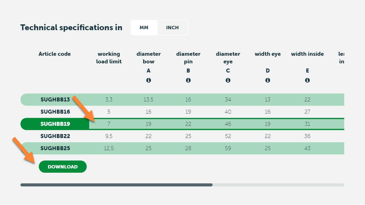
If you go to the product pages of individual products on this website, you can download the CAD-drawing (3D) of that product:
- On the product page, go to the table with dimensions
- Select the productsize that you are interested in
- A Download button will appear
If no Download button appears, no CAD-drawing for this product is available.
Note: Main dimensions, general info and warnings can be found in our latest catalogue.
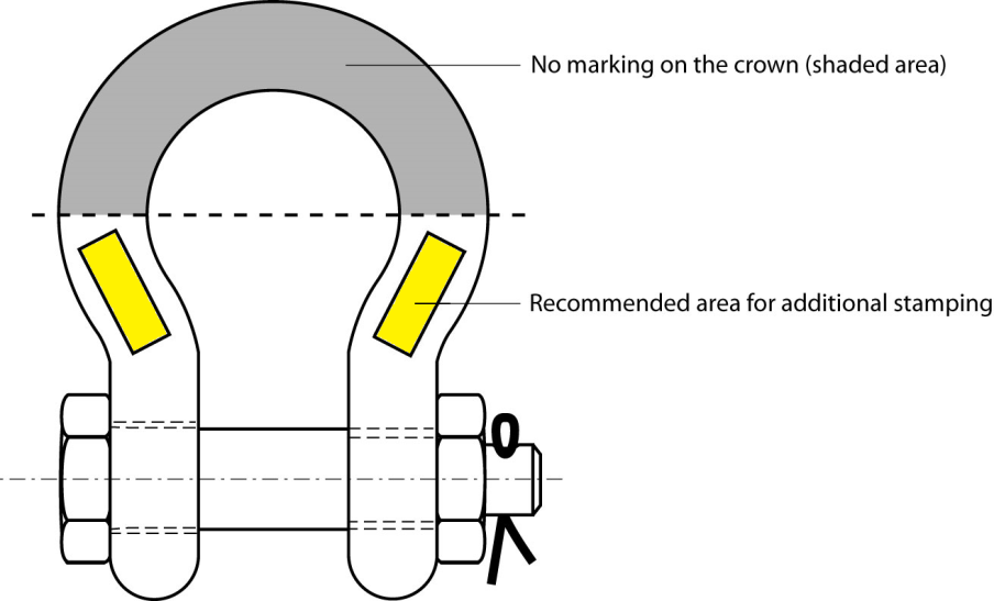
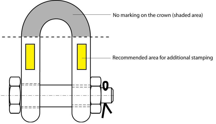
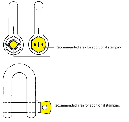
If the recommendations in this product information are followed performance of the shackles is guaranteed:
- permanent identification marks, or symbols, are to be made by dot peen marking or with stamps having rounded profiles (low stress stamps).
- the number of marks on a shackle is to be kept to the minimum.
- the use of fractions and oblique strokes is to be avoided and a dot or hyphen is preferable to a dividing line.
- values of WLL are, generally, to be marked to one place of decimals (except for 0.25 and 0.75) up to 100 t and in integers thereafter. The word “tonnes” may be abbreviated to “t”.
- recommended sizes of marks are
- Diameter of part to be marked > recommended size of mark
- less then 12.5 mm > 3.0 mm
- 12.5 to 26 mm > 4.5 mm
- over 26 mm > 6.0 mm
Typical arrangements of marks can be found in the following illustrations.
FAQ-Reference: PI-05-03. Rev 0.
It is required that shackles are regularly inspected and that the inspection should take place in accordance with the safety standards given in the country of use. This is required because the products in use may be affected by wear, misuse, overloading etc. with a consequence of deformation and alteration of the material structure. Inspection should take place at least every six months and even more frequently when the shackles are used in severe operating conditions.
Shackles should be inspected to ensure that:
- all markings are legible;
- the body and pin are both identifiable as being of the same size, type and make;
- the threads of the pin and the body are undamaged;
- for a safety bolt type shackle is used with the split cotter pin;
- the body and the pin are not distorted or unduly worn;
- the body and pin are free from nicks, gouges, cracks and corrosion;
- shackles are not heat treated as this may affect their Working Load Limit;
- the shackle is not modified, repaired or reshaped by welding, heating, machining or bending as this will affect the Working Load Limit;
Remove the shackle from service if:
- all markings are not clearly legible;
- body and pin can not be identified as being from same size, type and make;
- the threads of the pin and/or body are damaged;
- for a safety bolt type shackle the split cotter pin is missing;
- the body and/or pin is distorted or unduly worn, the maximum allowable wear is 10% of the original dimension;
- the body and/or pin is not free from nicks, gouges, cracks or corrosion;
- the shackle has been exposed to any heat treatment;
- the shackle is modified, repaired or reshaped by welding, heating, machining or bending;
- t is expected that before the next periodical inspection any of the inspection criteria above will not be passed;
FAQ-Reference: PI-06-01. Rev: 0.
No! Green Pin® products are treated with well designed heat treatment, which results in a certain Minimum Break Load and other specific mechanical properties. These properties will be destroyed by the heat of welding. It even can initiate extreme hard spots and initial cracks, that will decrease the strength and fatigue life dramatically. An exception is made for Green Pin® GH and PAS products, as these need to be welded to a surface to function. For these items, please follow the instructions that are available at Green Pin® sales.
FAQ-Reference PI-07-02 Rev. B
Please download it here.
Please find the answer in this document.
BN = Bolt & Nut, or safety bolt
CL = Clevis
CP = Cotter Pin
D = D-Handle
E = Eye
EE = Eye-Eye
EJ = Eye-Jaw
EH = Eye-Hook
F = F-Handle
FN = Fixed Nut
FP = Flush Pin
GR10 = Grade 10
GR5 = Grade 5
GR8 = Grade 8
HH = Hook-Hook
HK = Hook
H-type = Horizontal
JJ = Jaw-Jaw
ROV = Remotely Operated Vehicle
S = Shackle
S/S = Stainless Steel
SC = Screw Collar, or Screw Pin
SCL = Swivel Clevis
SE = Swivel Eye
SQ = Square headed Screw Pin
U-type = Universal (Horizontal and Vertical)
V-type = Vertical
High load capacity, grade 8 shackle with safety bolt
Highlights
 Saves up to 20% on cost of wire rope
- Improves safety thanks to multiple handling points and RFID-tracking
- Unique Green Pin® design (patent pending)
- Best choice for heavy lifting projects
- Superior stock availability of 99%
Description
The Green Pin Power Sling® Shackle BN is specially developed for heavy lifting. It is the top product in the Green Pin® shackle assortment and the wider lifting industry. The Green Pin Power Sling® Shackle BN has a bending efficiency of 85%. Its shackle crown is the widest in the industry (10% more than shackles of the previous generation) and has an optimal D/d ratio. Furthermore, the areas of the Power Sling® shackle that endure the highest stress have been reinforced. As a result, the Power Sling® lets you save up to 20% on synthetic- and wire rope costs. The long-term performance of the Power Sling® has been scrutinized with tensile- and fatigue testing, subjecting it to more than 40.000 cycles (the API norm specifies 20.000 cycles). Each shackle is proofload tested to twice the working load limit. Ductility of the steel has also been checked at temperatures as low as minus 40 °Celsius degree (-40 °F). Safety and efficiency for riggers are other key benefits of the Power Sling®. The Power Sling® is equipped with six handling points to the body and several more on the pin (larger sizes have more handling points than smaller sizes). Many such handling points are smaller shackles that are attached to the main shackle. Lifting the Power Sling® into place becomes a much safer and easier activity as a result. The Power Sling® can be supplied with a variety of certificates. The Green Pin Power Sling® Shackle BN is available in a range with a working load limit from 125 to 1550T. More information (product video, brochure) can be found on the website http://greenpin.com/power.
Product details
- ProductcodeP-6043
- Materialbow and pin alloy steel, Grade 8, quenched and tempered
- Safety factorMBL equals 5 x WLL
- Finishshackle bow painted silver, pin painted green
- Certification 2.1 2.2 3.1 MTCb LROS MPIb USb DNVGL-ST-0378 CE DNV-GL-ST-0377
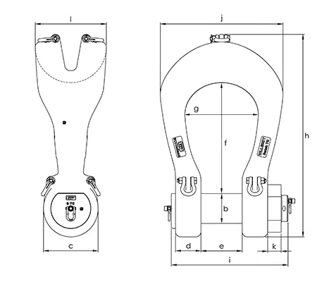
| Article code | working load limit | Weight shackle pin |
|
|
|
|
|
|
|
|
|
|
|
Net weight
(kg) |
|---|---|---|---|---|---|---|---|---|---|---|---|---|---|---|
| SLPGP0125 | 125 | 16,83 | 81 | 165 | 89 | 134 | 365 | 220 | 632 | 382 | 370 | 36 | 205 | 95 |
| SLPGP0150 | 150 | 25,83 | 95 | 182 | 90 | 144 | 390 | 250 | 703 | 408 | 420 | 42 | 248 | 134 |
| SLPGP0200 | 200 | 35,1 | 105 | 204 | 100 | 154 | 480 | 276 | 838 | 446 | 474 | 47 | 290 | 195 |
| SLPGP0250 | 250 | 54,2 | 120 | 238 | 114 | 174 | 540 | 300 | 938 | 503 | 513 | 60 | 314 | 271 |
| SLPGP0300 | 300 | 71,3 | 134 | 260 | 125 | 189 | 600 | 350 | 1032 | 550 | 604 | 60 | 345 | 368 |
| SLPGP0400 | 400 | 122,2 | 160 | 305 | 144 | 224 | 620 | 370 | 1123 | 645 | 653 | 80 | 392 | 563 |
| SLPGP0500 | 500 | 163,6 | 180 | 340 | 157 | 255 | 680 | 450 | 1239 | 714 | 763 | 85 | 440 | 786 |
| SLPGP0600 | 600 | 220,6 | 200 | 365 | 175 | 280 | 741 | 490 | 1354 | 788 | 818 | 90 | 475 | 1009 |
| SLPGP0700 | 700 | 288,7 | 215 | 405 | 195 | 320 | 751 | 540 | 1415 | 879 | 893 | 100 | 512 | 1288 |
| SLPGP0800 | 800 | 353,6 | 230 | 430 | 205 | 347 | 851 | 554 | 1547 | 945 | 917 | 108 | 536 | 1503 |
| SLPGP0900 | 900 | 472,7 | 255 | 476 | 220 | 373 | 852 | 580 | 1599 | 1013 | 972 | 120 | 560 | 1849 |
| SLPGP1000 | 1000 | 571 | 270 | 500 | 237 | 405 | 851 | 614 | 1643 | 1085 | 1022 | 125 | 590 | 2188 |
| Article code | working load limit | Weight shackle pin |
|
|
|
|
|
|
|
|
|
|
|
Net weight
(kg) |
|---|---|---|---|---|---|---|---|---|---|---|---|---|---|---|
| SLPGP1250 | 1250 | 722 | 300 | 570 | 251 | 436 | 930 | 650 | 1813 | 1144 | 1144 | 100 | 670 | 2933 |
| SLPGP1550 | 1550 | 881 | 320 | 590 | 276 | 481 | 950 | 680 | 1890 | 1256 | 1210 | 106 | 704 | 3558 |
| Article code | working load limit | Weight shackle pin |
|
|
|
|
|
|
|
|
|
|
|
Net weight
(LBS) |
|---|---|---|---|---|---|---|---|---|---|---|---|---|---|---|
| SLPGP0125 | 125 | 37,1 | 3 3/16 | 6 1/2 | 3 1/2 | 5 9/32 | 14 3/8 | 8 21/32 | 24 7/8 | 15 1/32 | 14 9/16 | 1 13/32 | 8 1/16 | 209 |
| SLPGP0150 | 150 | 56,95 | 3 3/4 | 7 5/32 | 3 17/32 | 5 21/32 | 15 11/32 | 9 27/32 | 27 11/16 | 16 1/16 | 16 17/32 | 1 21/32 | 9 3/4 | 295 |
| SLPGP0200 | 200 | 77,38 | 4 1/8 | 8 1/32 | 3 15/16 | 6 1/16 | 18 29/32 | 10 7/8 | 33 | 17 9/16 | 18 21/32 | 1 27/32 | 11 13/32 | 430 |
| SLPGP0250 | 250 | 119,49 | 4 23/32 | 9 3/8 | 4 1/2 | 6 27/32 | 21 1/4 | 11 13/16 | 36 15/16 | 19 13/16 | 20 3/16 | 2 3/8 | 12 3/8 | 598 |
| SLPGP0300 | 300 | 157,19 | 5 9/32 | 10 1/4 | 4 29/32 | 7 7/16 | 23 5/8 | 13 25/32 | 40 5/8 | 21 21/32 | 23 25/32 | 2 3/8 | 13 19/32 | 811 |
| SLPGP0400 | 400 | 269,4 | 6 5/16 | 12 | 5 21/32 | 8 13/16 | 24 13/32 | 14 9/16 | 44 7/32 | 25 13/32 | 25 23/32 | 3 5/32 | 15 7/16 | 1241 |
| SLPGP0500 | 500 | 360,68 | 7 3/32 | 13 3/8 | 6 3/16 | 10 1/32 | 26 25/32 | 17 23/32 | 48 25/32 | 28 1/8 | 30 1/32 | 3 11/32 | 17 5/16 | 1733 |
| SLPGP0600 | 600 | 486,34 | 7 7/8 | 14 3/8 | 6 7/8 | 11 1/32 | 29 3/16 | 19 9/32 | 53 5/16 | 31 1/32 | 32 7/32 | 3 17/32 | 18 11/16 | 2225 |
| SLPGP0700 | 700 | 636,47 | 8 15/32 | 15 15/16 | 7 11/16 | 12 19/32 | 29 9/16 | 21 1/4 | 55 23/32 | 34 19/32 | 35 5/32 | 3 15/16 | 20 5/32 | 2840 |
| SLPGP0800 | 800 | 779,55 | 9 1/16 | 16 15/16 | 8 1/16 | 13 21/32 | 33 1/2 | 21 13/16 | 60 29/32 | 37 7/32 | 36 3/32 | 4 1/4 | 21 3/32 | 3314 |
| SLPGP0900 | 900 | 1042,13 | 10 1/32 | 18 3/4 | 8 21/32 | 14 11/16 | 33 17/32 | 22 27/32 | 62 15/16 | 39 7/8 | 38 9/32 | 4 23/32 | 22 1/16 | 4077 |
| SLPGP1000 | 1000 | 1258,84 | 10 5/8 | 19 11/16 | 9 11/32 | 15 15/16 | 33 1/2 | 24 3/16 | 64 11/16 | 42 23/32 | 40 1/4 | 4 29/32 | 23 7/32 | 4825 |
| Article code | working load limit | Weight shackle pin |
|
|
|
|
|
|
|
|
|
|
|
Net weight
(LBS) |
|---|---|---|---|---|---|---|---|---|---|---|---|---|---|---|
| SLPGP1250 | 1250 | 1591,74 | 11 13/16 | 22 7/16 | 9 7/8 | 17 5/32 | 36 5/8 | 25 19/32 | 71 3/8 | 45 1/32 | 45 1/32 | 3 15/16 | 26 3/8 | 6467 |
| SLPGP1550 | 1550 | 1942,27 | 12 19/32 | 23 7/32 | 10 7/8 | 18 15/16 | 37 13/32 | 26 25/32 | 74 13/32 | 49 7/16 | 47 5/8 | 4 3/16 | 27 23/32 | 7845 |