Green Pin® Locking Clamp ROV Shackle
Release ROV shackle (grade 8) with locking clamp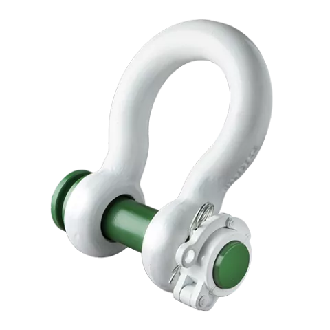
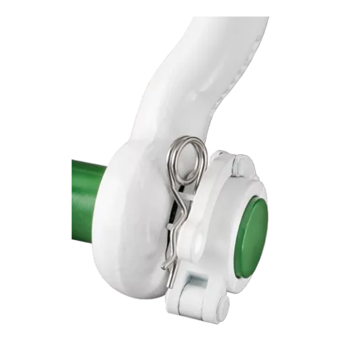

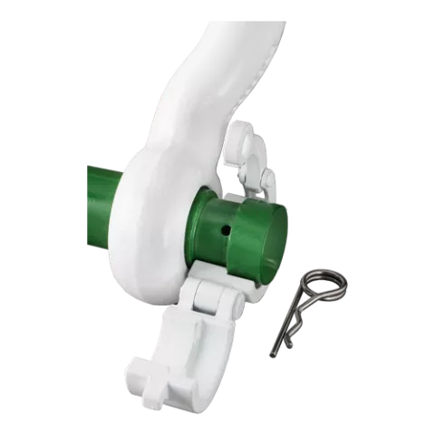
- Powerful locking system ensures load is not released unintentionally
- Locking system is easy to handle for the ROV pilot
- Designed for under water use in harsh conditions
- White coating optimizes visibility under water
- Developed specifically for sub-sea applications
The Green Pin® Locking Clamp ROV Shackle is perfect for release operations with a remotely operated vehicle (ROV). The grade 8 shackle has been specially developed for sub-sea applications and is easy to handle for the ROV pilot. The Green Pin® Locking Clamp ROV Shackle has a powerful locking system which ensures that the load will not be released before you want it to. The white coating of the Green Pin® Locking Clamp ROV Shackle optimizes visibility under water and ensures its long-term durability. The ROV shackle is available in a range with a working load limit from 6.5 up to 250 ton.
More-
ProductcodeP-5365
-
Materialbow and pin alloy steel, Grade 8, Polar Quality, quenched and tempered
-
Safety factorMBL equals 6 x WLLfor shackles with WLL 120 t and up the MBL equals 5 x WLL
-
Finishshackle bow painted white, pin painted green
-
Temp. range-60°C up to +200°C
-
Certification
- 2.1
- 2.2
- 3.1
- MTCa
- MTCb
- LROS
- CE
-
Notesupplied without wires, design your own wiring plan
| Article code |
working load limit
(ton)
|
working load limit
(ton)
|
Weight shackle pin
(kg)
|
Weight shackle pin
(lb)
|
Net weight
(kg)
|
Net weight
(lbs)
|
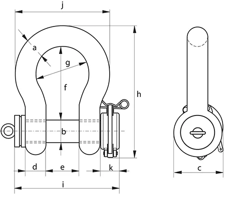
diameter bow
(mm)
A
|
diameter bow (inch)
A
|
diameter pin (inch)
B
|
diameter pin
(mm)
B
|
diameter eye
(mm)
C
|
diameter eye (inch)
C
|
width eye (inch)
D
|
width eye
(mm)
D
|
width inside (inch)
E
|
width inside
(mm)
E
|
length inside
(mm)
F
|
length inside (inch)
F
|
width bow (inch)
G
|
width bow
(mm)
G
|
length
(mm)
H
|
length (inch)
H
|
length bolt
(mm)
I
|
length bolt (inch)
I
|
width (inch)
J
|
width
(mm)
J
|
width locking clamp (inch)
K
|
width locking clamp
(mm)
K
|
Net weight (KG) | Net weight (LBS) | |
|---|---|---|---|---|---|---|---|---|---|---|---|---|---|---|---|---|---|---|---|---|---|---|---|---|---|---|---|---|---|---|---|
| POGHMB22ROVRLLC | 6,5 | 1,22 | 2.17 | 22 | 25 | 52 | 22 | 36 | 83 | 58 | 164 | 140 | 102 | 45 | 2.17 | ||||||||||||||||
| POGHMB22ROVRLLC | 6,5 | 2,69 | 4.79 | 7/8 | 1 | 2 1/32 | 7/8 | 1 7/16 | 3 9/32 | 2 9/32 | 6 7/16 | 5 17/32 | 4 | 1 25/32 | 4.79 | ||||||||||||||||
| POGHMB28ROVRLLC | 9,5 | 2 | 4.25 | 28 | 32 | 66 | 28 | 47 | 108 | 75 | 200 | 172 | 131 | 48 | 4.25 | ||||||||||||||||
| POGHMB28ROVRLLC | 9,5 | 4,4 | 9.36 | 1 1/8 | 1 1/4 | 2 19/32 | 1 1/8 | 1 7/8 | 4 1/4 | 2 15/16 | 7 7/8 | 6 3/4 | 5 5/32 | 1 29/32 | 9.36 | ||||||||||||||||
| POGHMB32ROVRLLC | 12 | 2,26 | 5.36 | 32 | 35 | 72 | 32 | 51 | 115 | 83 | 213 | 184 | 147 | 48 | 5.36 | ||||||||||||||||
| POGHMB32ROVRLLC | 12 | 4,98 | 11.8 | 1 1/4 | 1 3/8 | 2 13/16 | 1 9/32 | 2 | 4 17/32 | 3 9/32 | 8 3/8 | 7 1/4 | 5 25/32 | 1 29/32 | 11.8 | ||||||||||||||||
| POGHMB38ROVRLLC | 17 | 3,86 | 9.27 | 38 | 42 | 88 | 38 | 60 | 146 | 99 | 266 | 209 | 175 | 48 | 9.27 | ||||||||||||||||
| POGHMB38ROVRLLC | 17 | 8,51 | 20.4 | 1 1/2 | 1 5/8 | 3 1/2 | 1 17/32 | 2 11/32 | 5 3/4 | 3 29/32 | 10 1/2 | 8 1/4 | 6 7/8 | 1 29/32 | 20.4 | ||||||||||||||||
| POGHMB45ROVRLLC | 25 | 5,62 | 14.6 | 45 | 50 | 103 | 45 | 74 | 178 | 126 | 309 | 243 | 216 | 48 | 14.6 | ||||||||||||||||
| POGHMB45ROVRLLC | 25 | 12,38 | 32.2 | 1 3/4 | 2 | 4 1/32 | 1 25/32 | 2 29/32 | 7 | 4 15/16 | 12 5/32 | 9 19/32 | 8 17/32 | 1 29/32 | 32.2 | ||||||||||||||||
| POGHMB50ROVRLLC | 35 | 7,89 | 20.7 | 50 | 57 | 116 | 50 | 83 | 197 | 138 | 350 | 269 | 238 | 48 | 20.7 | ||||||||||||||||
| POGHMB50ROVRLLC | 35 | 17,4 | 45.7 | 2 | 2 1/4 | 4 9/16 | 1 31/32 | 3 9/32 | 7 3/4 | 5 7/16 | 13 25/32 | 10 19/32 | 9 3/8 | 1 29/32 | 45.7 | ||||||||||||||||
| POGHMB57ROVRLLC | 42,5 | 10,6 | 28.3 | 57 | 65 | 130 | 57 | 95 | 222 | 160 | 377 | 301 | 274 | 48 | 28.3 | ||||||||||||||||
| POGHMB57ROVRLLC | 42,5 | 23,37 | 62.5 | 2 1/4 | 2 9/16 | 5 1/8 | 2 1/4 | 3 3/4 | 8 3/4 | 6 9/32 | 14 13/16 | 11 7/8 | 10 25/32 | 1 29/32 | 62.5 | ||||||||||||||||
| POGHMB65ROVRLLC | 55 | 12,84 | 41.0 | 65 | 70 | 145 | 65 | 105 | 260 | 180 | 440 | 329 | 310 | 48 | 41 | ||||||||||||||||
| POGHMB65ROVRLLC | 55 | 28,31 | 90.4 | 2 1/2 | 2 3/4 | 5 23/32 | 2 9/16 | 4 1/8 | 10 1/4 | 7 3/32 | 17 11/32 | 12 15/16 | 12 3/16 | 1 29/32 | 90.4 | ||||||||||||||||
| POGHMB75ROVRLLC | 85 | 18,69 | 61.0 | 75 | 83 | 162 | 75 | 127 | 329 | 190 | 527 | 375 | 340 | 48 | 61 | ||||||||||||||||
| POGHMB75ROVRLLC | 85 | 41,2 | 135 | 3 | 3 1/4 | 6 11/32 | 2 15/16 | 5 | 12 15/16 | 7 1/2 | 20 3/4 | 14 3/4 | 13 3/8 | 1 29/32 | 135 | ||||||||||||||||
| HDPOHM0120ROVRLLC | 120 | 29 | 110 | 95 | 95 | 208 | 91 | 147 | 400 | 238 | 647 | 440 | 428 | 60 | 110 | ||||||||||||||||
| HDPOHM0120ROVRLLC | 120 | 63,93 | 243 | 3 3/4 | 3 3/4 | 8 3/16 | 3 19/32 | 5 25/32 | 15 3/4 | 9 3/8 | 25 1/2 | 17 11/32 | 16 7/8 | 2 11/32 | 243 | ||||||||||||||||
| HDPOHM0150ROVRLLC | 150 | 38,77 | 160 | 105 | 108 | 238 | 102 | 169 | 410 | 275 | 688 | 490 | 485 | 60 | 160 | ||||||||||||||||
| HDPOHM0150ROVRLLC | 150 | 85,47 | 353 | 4 1/8 | 4 1/4 | 9 3/8 | 4 | 6 5/8 | 16 5/32 | 10 13/16 | 27 3/32 | 19 5/16 | 19 1/8 | 2 11/32 | 353 | ||||||||||||||||
| HDPOHM0200ROVRLLC | 200 | 66,06 | 235 | 120 | 130 | 279 | 113 | 179 | 513 | 290 | 838 | 520 | 530 | 60 | 235 | ||||||||||||||||
| HDPOHM0200ROVRLLC | 200 | 145,64 | 518 | 4 23/32 | 5 1/8 | 11 | 4 7/16 | 7 1/32 | 20 3/16 | 11 7/16 | 33 | 20 1/2 | 20 7/8 | 2 11/32 | 518 | ||||||||||||||||
| HDPOHM0250ROVRLLC | 250 | 69 | 285 | 130 | 140 | 299 | 118 | 205 | 554 | 305 | 904 | 560 | 565 | 60 | 285 | ||||||||||||||||
| HDPOHM0250ROVRLLC | 250 | 152,13 | 628 | 5 1/8 | 5 1/2 | 11 25/32 | 4 5/8 | 8 3/32 | 21 13/16 | 12 | 35 19/32 | 22 1/32 | 22 1/4 | 2 11/32 | 628 |
Do you have questions about this product? Don't hesitate to contact us.
Product video
Frequently Asked Questions
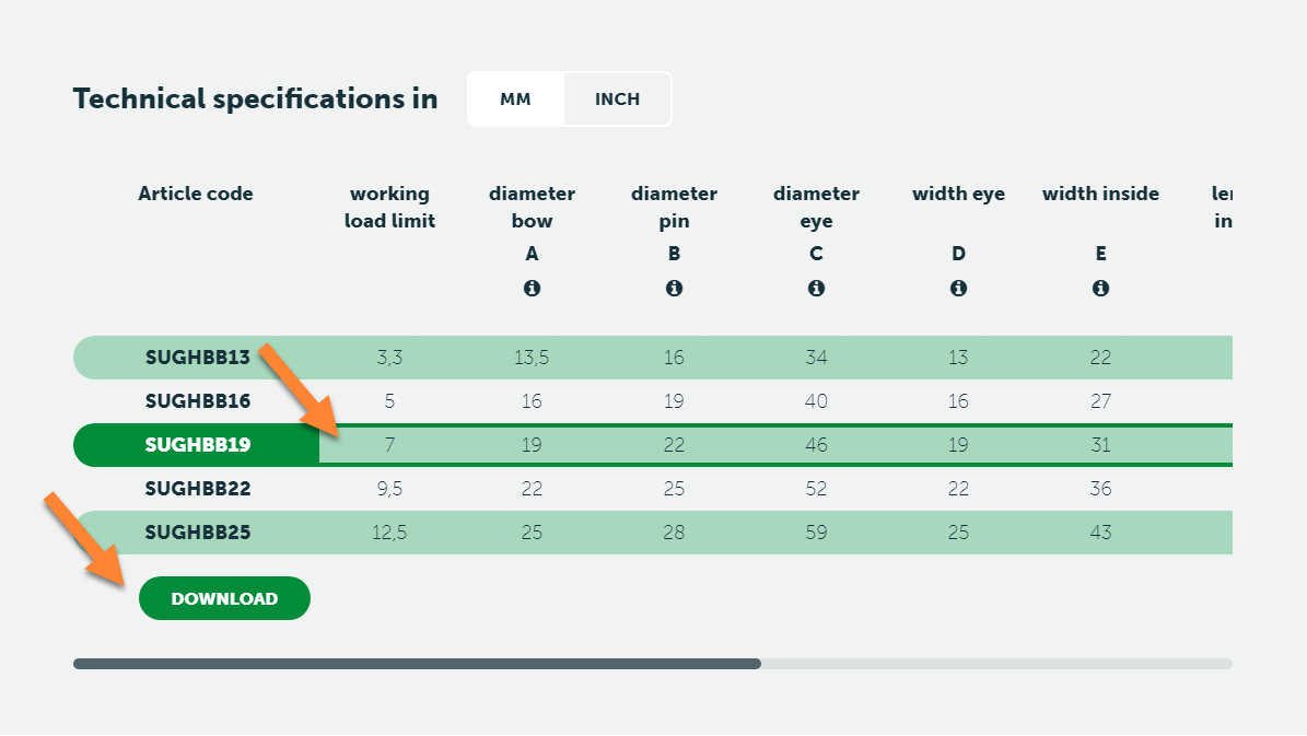
If you go to the product pages of individual products on this website, you can download the CAD-drawing (3D) of that product:
- On the product page, go to the table with dimensions
- Select the productsize that you are interested in
- A Download button will appear
If no Download button appears, no CAD-drawing for this product is available.
Note: Main dimensions, general info and warnings can be found in our latest catalogue.
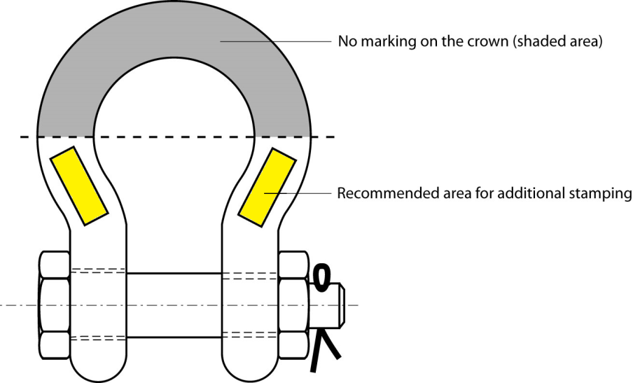
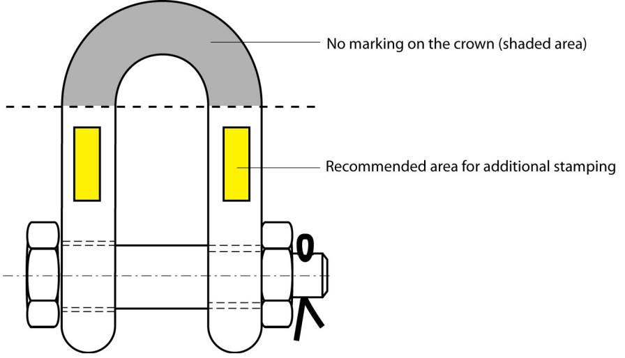
If the recommendations in this product information are followed performance of the shackles is guaranteed:
- permanent identification marks, or symbols, are to be made by dot peen marking or with stamps having rounded profiles (low stress stamps).
- laser markings are allowed as long as the heat of the laser does not influence the material structure and properties in a negative way. The laser marking must be legibly and indelibly marked in a place where the markings will not be removed by use.
- the number of marks on a shackle is to be kept to the minimum.
- the use of fractions and oblique strokes is to be avoided and a dot or hyphen is preferable to a dividing line.
- values of WLL are, generally, to be marked to one place of decimals (except for 0.25 and 0.75) up to 100 t and in integers thereafter. The word “tonnes” may be abbreviated to “t”.
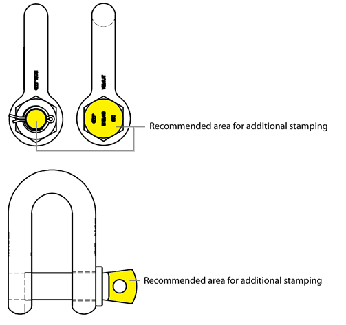
- recommended sizes of marks are
- Diameter of part to be marked > recommended size of mark
- less then 12.5 mm > 3.0 mm
- 12.5 to 26 mm > 4.5 mm
- over 26 mm > 6.0 mm
Typical arrangements of marks can be found in the following illustrations.
FAQ-Reference: PI-05-03. Rev 0.
It is required that shackles are regularly inspected and that the inspection should take place in accordance with the safety standards given in the country of use. This is required because the products in use may be affected by wear, misuse, overloading etc. with a consequence of deformation and alteration of the material structure. Inspection should take place at least every six months and even more frequently when the shackles are used in severe operating conditions.
Shackles should be inspected to ensure that:
- all markings are legible;
- the body and pin are both identifiable as being of the same size, type and make;
- the threads of the pin and the body are undamaged;
- for a safety bolt type shackle is used with the split cotter pin;
- the body and the pin are not distorted or unduly worn;
- the body and pin are free from nicks, gouges, cracks and corrosion;
- shackles are not heat treated as this may affect their Working Load Limit;
- the shackle is not modified, repaired or reshaped by welding, heating, machining or bending as this will affect the Working Load Limit;
Remove the shackle from service if:
- all markings are not clearly legible;
- body and pin can not be identified as being from same size, type and make;
- the threads of the pin and/or body are damaged;
- for a safety bolt type shackle the split cotter pin is missing;
- the body and/or pin is distorted or unduly worn, the maximum allowable wear is 10% of the original dimension;
- the body and/or pin is not free from nicks, gouges, cracks or corrosion;
- the shackle has been exposed to any heat treatment;
- the shackle is modified, repaired or reshaped by welding, heating, machining or bending;
- t is expected that before the next periodical inspection any of the inspection criteria above will not be passed;
FAQ-Reference: PI-06-01. Rev: 0.
No! Green Pin® products are treated with well designed heat treatment, which results in a certain Minimum Break Load and other specific mechanical properties. These properties will be destroyed by the heat of welding. It even can initiate extreme hard spots and initial cracks, that will decrease the strength and fatigue life dramatically. An exception is made for Green Pin® GH and PAS products, as these need to be welded to a surface to function. For these items, please follow the instructions that are available at Green Pin® sales.
Please find the user manual here.
BN = Bolt & Nut, or safety bolt
CL = Clevis
CP = Cotter Pin
D = D-Handle
E = Eye
EE = Eye-Eye
EJ = Eye-Jaw
EH = Eye-Hook
F = F-Handle
FN = Fixed Nut
FP = Flush Pin
GR10 = Grade 10
GR5 = Grade 5
GR8 = Grade 8
HH = Hook-Hook
HK = Hook
H-type = Horizontal
JJ = Jaw-Jaw
ROV = Remotely Operated Vehicle
S = Shackle
S/S = Stainless Steel
SC = Screw Collar, or Screw Pin
SCL = Swivel Clevis
SE = Swivel Eye
SQ = Square headed Screw Pin
U-type = Universal (Horizontal and Vertical)
V-type = Vertical
Green Pin® shackles are known for their robust quality and versatility, are differentiated across various attributes which suit specific needs in different industries, including construction, maritime, and heavy lifting. They differ in grade, certificate, crown width, end fitting, number of safeties and special features. To discover all Green Pin shackles, visit the shackles category page here.
Release ROV shackle (grade 8) with locking clamp
Highlights
 Powerful locking system ensures load is not released unintentionally
- Locking system is easy to handle for the ROV pilot
- Designed for under water use in harsh conditions
- White coating optimizes visibility under water
- Developed specifically for sub-sea applications
Description
The Green Pin® Locking Clamp ROV Shackle is perfect for release operations with a remotely operated vehicle (ROV). The grade 8 shackle has been specially developed for sub-sea applications and is easy to handle for the ROV pilot. The Green Pin® Locking Clamp ROV Shackle has a powerful locking system which ensures that the load will not be released before you want it to. The white coating of the Green Pin® Locking Clamp ROV Shackle optimizes visibility under water and ensures its long-term durability. The ROV shackle is available in a range with a working load limit from 6.5 up to 250 ton.
Product details
- ProductcodeP-5365
- Materialbow and pin alloy steel, Grade 8, Polar Quality, quenched and tempered
- Safety factorMBL equals 6 x WLLfor shackles with WLL 120 t and up the MBL equals 5 x WLL
- Finishshackle bow painted white, pin painted green
- Temp. range-60°C up to +200°C
- Certification 2.1 2.2 3.1 MTCa MTCb LROS CE
- Notesupplied without wires, design your own wiring plan
| Article code | working load limit | Weight shackle pin | Net weight |
|
|
|
|
|
|
|
|
|
|
|
Net weight
(kg) |
|---|---|---|---|---|---|---|---|---|---|---|---|---|---|---|---|
| POGHMB22ROVRLLC | 6,5 | 1,22 | 2.17 | 22 | 25 | 52 | 22 | 36 | 83 | 58 | 164 | 140 | 102 | 45 | 2.17 |
| POGHMB28ROVRLLC | 9,5 | 2 | 4.25 | 28 | 32 | 66 | 28 | 47 | 108 | 75 | 200 | 172 | 131 | 48 | 4.25 |
| POGHMB32ROVRLLC | 12 | 2,26 | 5.36 | 32 | 35 | 72 | 32 | 51 | 115 | 83 | 213 | 184 | 147 | 48 | 5.36 |
| POGHMB38ROVRLLC | 17 | 3,86 | 9.27 | 38 | 42 | 88 | 38 | 60 | 146 | 99 | 266 | 209 | 175 | 48 | 9.27 |
| POGHMB45ROVRLLC | 25 | 5,62 | 14.6 | 45 | 50 | 103 | 45 | 74 | 178 | 126 | 309 | 243 | 216 | 48 | 14.6 |
| POGHMB50ROVRLLC | 35 | 7,89 | 20.7 | 50 | 57 | 116 | 50 | 83 | 197 | 138 | 350 | 269 | 238 | 48 | 20.7 |
| POGHMB57ROVRLLC | 42,5 | 10,6 | 28.3 | 57 | 65 | 130 | 57 | 95 | 222 | 160 | 377 | 301 | 274 | 48 | 28.3 |
| POGHMB65ROVRLLC | 55 | 12,84 | 41.0 | 65 | 70 | 145 | 65 | 105 | 260 | 180 | 440 | 329 | 310 | 48 | 41 |
| POGHMB75ROVRLLC | 85 | 18,69 | 61.0 | 75 | 83 | 162 | 75 | 127 | 329 | 190 | 527 | 375 | 340 | 48 | 61 |
| HDPOHM0120ROVRLLC | 120 | 29 | 110 | 95 | 95 | 208 | 91 | 147 | 400 | 238 | 647 | 440 | 428 | 60 | 110 |
| HDPOHM0150ROVRLLC | 150 | 38,77 | 160 | 105 | 108 | 238 | 102 | 169 | 410 | 275 | 688 | 490 | 485 | 60 | 160 |
| HDPOHM0200ROVRLLC | 200 | 66,06 | 235 | 120 | 130 | 279 | 113 | 179 | 513 | 290 | 838 | 520 | 530 | 60 | 235 |
| Article code | working load limit | Weight shackle pin | Net weight |
|
|
|
|
|
|
|
|
|
|
|
Net weight
(kg) |
|---|---|---|---|---|---|---|---|---|---|---|---|---|---|---|---|
| HDPOHM0250ROVRLLC | 250 | 69 | 285 | 130 | 140 | 299 | 118 | 205 | 554 | 305 | 904 | 560 | 565 | 60 | 285 |
| Article code | working load limit | Weight shackle pin | Net weight |
|
|
|
|
|
|
|
|
|
|
|
Net weight
(LBS) |
|---|---|---|---|---|---|---|---|---|---|---|---|---|---|---|---|
| POGHMB22ROVRLLC | 6,5 | 2,69 | 4.79 | 7/8 | 1 | 2 1/32 | 7/8 | 1 7/16 | 3 9/32 | 2 9/32 | 6 7/16 | 5 17/32 | 4 | 1 25/32 | 4.79 |
| POGHMB28ROVRLLC | 9,5 | 4,4 | 9.36 | 1 1/8 | 1 1/4 | 2 19/32 | 1 1/8 | 1 7/8 | 4 1/4 | 2 15/16 | 7 7/8 | 6 3/4 | 5 5/32 | 1 29/32 | 9.36 |
| POGHMB32ROVRLLC | 12 | 4,98 | 11.8 | 1 1/4 | 1 3/8 | 2 13/16 | 1 9/32 | 2 | 4 17/32 | 3 9/32 | 8 3/8 | 7 1/4 | 5 25/32 | 1 29/32 | 11.8 |
| POGHMB38ROVRLLC | 17 | 8,51 | 20.4 | 1 1/2 | 1 5/8 | 3 1/2 | 1 17/32 | 2 11/32 | 5 3/4 | 3 29/32 | 10 1/2 | 8 1/4 | 6 7/8 | 1 29/32 | 20.4 |
| POGHMB45ROVRLLC | 25 | 12,38 | 32.2 | 1 3/4 | 2 | 4 1/32 | 1 25/32 | 2 29/32 | 7 | 4 15/16 | 12 5/32 | 9 19/32 | 8 17/32 | 1 29/32 | 32.2 |
| POGHMB50ROVRLLC | 35 | 17,4 | 45.7 | 2 | 2 1/4 | 4 9/16 | 1 31/32 | 3 9/32 | 7 3/4 | 5 7/16 | 13 25/32 | 10 19/32 | 9 3/8 | 1 29/32 | 45.7 |
| POGHMB57ROVRLLC | 42,5 | 23,37 | 62.5 | 2 1/4 | 2 9/16 | 5 1/8 | 2 1/4 | 3 3/4 | 8 3/4 | 6 9/32 | 14 13/16 | 11 7/8 | 10 25/32 | 1 29/32 | 62.5 |
| POGHMB65ROVRLLC | 55 | 28,31 | 90.4 | 2 1/2 | 2 3/4 | 5 23/32 | 2 9/16 | 4 1/8 | 10 1/4 | 7 3/32 | 17 11/32 | 12 15/16 | 12 3/16 | 1 29/32 | 90.4 |
| POGHMB75ROVRLLC | 85 | 41,2 | 135 | 3 | 3 1/4 | 6 11/32 | 2 15/16 | 5 | 12 15/16 | 7 1/2 | 20 3/4 | 14 3/4 | 13 3/8 | 1 29/32 | 135 |
| HDPOHM0120ROVRLLC | 120 | 63,93 | 243 | 3 3/4 | 3 3/4 | 8 3/16 | 3 19/32 | 5 25/32 | 15 3/4 | 9 3/8 | 25 1/2 | 17 11/32 | 16 7/8 | 2 11/32 | 243 |
| HDPOHM0150ROVRLLC | 150 | 85,47 | 353 | 4 1/8 | 4 1/4 | 9 3/8 | 4 | 6 5/8 | 16 5/32 | 10 13/16 | 27 3/32 | 19 5/16 | 19 1/8 | 2 11/32 | 353 |
| HDPOHM0200ROVRLLC | 200 | 145,64 | 518 | 4 23/32 | 5 1/8 | 11 | 4 7/16 | 7 1/32 | 20 3/16 | 11 7/16 | 33 | 20 1/2 | 20 7/8 | 2 11/32 | 518 |
| Article code | working load limit | Weight shackle pin | Net weight |
|
|
|
|
|
|
|
|
|
|
|
Net weight
(LBS) |
|---|---|---|---|---|---|---|---|---|---|---|---|---|---|---|---|
| HDPOHM0250ROVRLLC | 250 | 152,13 | 628 | 5 1/8 | 5 1/2 | 11 25/32 | 4 5/8 | 8 3/32 | 21 13/16 | 12 | 35 19/32 | 22 1/32 | 22 1/4 | 2 11/32 | 628 |