Green Pin® Master Link EN1677-4
Grade 8 master link EN1677-4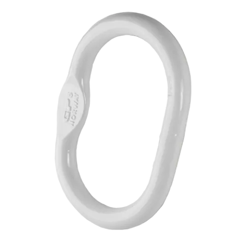
- Reliable Green Pin® quality and support
- Superior stock availability of 99%
The Green Pin® Master Link EN1677-4 is a single grade 8 master link according to European standard for components for sling EN 1677-4. This welded master single link is designed for a 1 or 2 leg sling. The flat on the eye enables the assembly with an omega link or on a thimble. The Green Pin® Master Link EN1677-4 is available in a range with a working load limit from 1.6 t. up to 125 t.
More-
ProductcodeMS
-
Materialalloy steel, Grade 8
-
Safety factorMBL equals 4 x WLL
-
Finishpainted white
-
Temp. range-40°C up to +200°C
-
Certification
- 2.1
- 2.2
- 3.1
- MTCb
- MPIa
-
StandardEN 1677-4
-
Notefrom 50 t without flat part
| Article code |
working load limit
(ton)
|
working load limit
(ton)
|
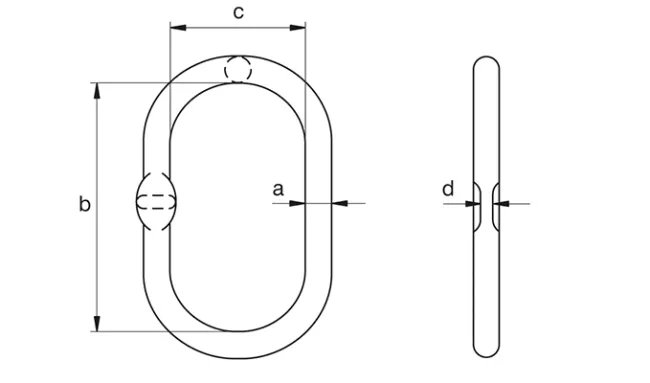
diameter (inch)
A
|
diameter
(mm)
A
|
length inside (inch)
B
|
length inside
(mm)
B
|
width inside (inch)
C
|
width inside
(mm)
C
|
thickness (inch)
D
|
thickness
(mm)
D
|
Net weight (KG) | Net weight (LBS) | |
|---|---|---|---|---|---|---|---|---|---|---|---|---|---|
| GPMS13 | 1,6 | 13 | 115 | 60 | 7 | 0.40 | |||||||
| GPMS13 | 1,6 | 1/2 | 4 17/32 | 2 3/8 | 9/32 | 0.88 | |||||||
| GPMS16 | 3,2 | 16 | 120 | 70 | 7 | 0.60 | |||||||
| GPMS16 | 3,2 | 5/8 | 4 23/32 | 2 3/4 | 9/32 | 1.32 | |||||||
| GPMS18 | 4,5 | 18 | 135 | 75 | 9 | 0.84 | |||||||
| GPMS18 | 4,5 | 11/16 | 5 5/16 | 2 15/16 | 11/32 | 1.85 | |||||||
| GPMS20 | 6,2 | 20 | 150 | 82 | 11 | 1.10 | |||||||
| GPMS20 | 6,2 | 3/4 | 5 29/32 | 3 17/32 | 7/16 | 2.43 | |||||||
| GPMS22 | 8,2 | 22 | 170 | 90 | 14 | 1.60 | |||||||
| GPMS22 | 8,2 | 7/8 | 6 11/16 | 3 17/32 | 9/16 | 3.53 | |||||||
| GPMS25 | 10,6 | 25 | 190 | 103 | 14 | 2.30 | |||||||
| GPMS25 | 10,6 | 1 | 7 1/2 | 4 1/16 | 9/16 | 5.07 | |||||||
| GPMS28 | 12,8 | 28 | 209 | 120 | 17 | 3.06 | |||||||
| GPMS28 | 12,8 | 1 1/8 | 8 7/32 | 4 23/32 | 21/32 | 6.75 | |||||||
| GPMS30 | 15,5 | 30 | 235 | 125 | 17 | 4.00 | |||||||
| GPMS30 | 15,5 | 1 3/16 | 9 1/4 | 4 29/32 | 21/32 | 8.82 | |||||||
| GPMS36 | 20 | 36 | 270 | 145 | 22 | 6.60 | |||||||
| GPMS36 | 20 | 1 3/8 | 10 5/8 | 5 23/32 | 7/8 | 14.6 | |||||||
| GPMS38 | 25 | 38 | 250 | 150 | 22 | 7.10 | |||||||
| GPMS38 | 25 | 1 1/2 | 9 27/32 | 5 29/32 | 7/8 | 15.7 | |||||||
| GPMS45 | 37 | 45 | 300 | 200 | 22 | 12.1 | |||||||
| GPMS45 | 37 | 1 3/4 | 11 13/16 | 7 7/8 | 7/8 | 26.7 | |||||||
| GPMS50 | 50 | 50 | 380 | 200 | 50 | 18.0 | |||||||
| GPMS50 | 50 | 2 | 15 | 7 7/8 | - | 39.7 | |||||||
| GPMS55 | 63 | 55 | 360 | 200 | 55 | 21.0 | |||||||
| GPMS55 | 63 | 2 3/16 | 14 3/16 | 7 7/8 | - | 46.3 | |||||||
| GPMS70 | 100 | 70 | 500 | 250 | 70 | 44.0 | |||||||
| GPMS70 | 100 | 2 3/4 | 19 11/16 | 9 27/32 | - | 97.0 | |||||||
| GPMS80 | 125 | 80 | 503 | 280 | 80 | 60.7 | |||||||
| GPMS80 | 125 | 3 1/8 | 19 13/16 | 11 1/32 | - | 134 |
Frequently Asked Questions
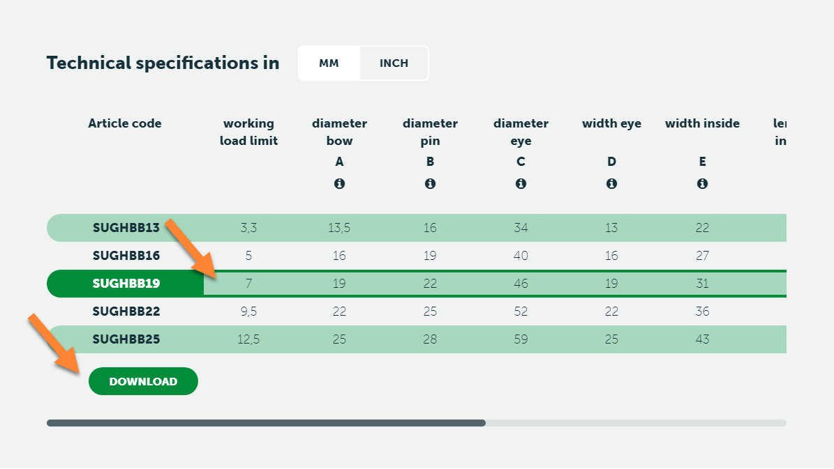
If you go to the product pages of individual products on this website, you can download the CAD-drawing (3D) of that product:
- On the product page, go to the table with dimensions
- Select the productsize that you are interested in
- A Download button will appear
If no Download button appears, no CAD-drawing for this product is available.
You can find the Working Load Limit tables for chain assemblies here:
No! Green Pin® products are treated with well designed heat treatment, which results in a certain Minimum Break Load and other specific mechanical properties. These properties will be destroyed by the heat of welding. It even can initiate extreme hard spots and initial cracks, that will decrease the strength and fatigue life dramatically. An exception is made for Green Pin® GH and PAS products, as these need to be welded to a surface to function. For these items, please follow the instructions that are available at Green Pin® sales.
BN = Bolt & Nut, or safety bolt
CL = Clevis
CP = Cotter Pin
D = D-Handle
E = Eye
EE = Eye-Eye
EJ = Eye-Jaw
EH = Eye-Hook
F = F-Handle
FN = Fixed Nut
FP = Flush Pin
GR10 = Grade 10
GR5 = Grade 5
GR8 = Grade 8
HH = Hook-Hook
HK = Hook
H-type = Horizontal
JJ = Jaw-Jaw
ROV = Remotely Operated Vehicle
S = Shackle
S/S = Stainless Steel
SC = Screw Collar, or Screw Pin
SCL = Swivel Clevis
SE = Swivel Eye
SQ = Square headed Screw Pin
U-type = Universal (Horizontal and Vertical)
V-type = Vertical
Green Pin® links are designed to meet a variety of industrial demands with their diverse range of specifications. These links are available in different grades, which determine their strength and load-bearing capacity, crucial for ensuring reliability in heavy-duty applications across sectors like construction, maritime, and lifting operations. To discover all Green Pin® links, visit the links category page here.
Grade 8 master link EN1677-4
Highlights
 Reliable Green Pin® quality and support
- Superior stock availability of 99%
Description
The Green Pin® Master Link EN1677-4 is a single grade 8 master link according to European standard for components for sling EN 1677-4. This welded master single link is designed for a 1 or 2 leg sling. The flat on the eye enables the assembly with an omega link or on a thimble. The Green Pin® Master Link EN1677-4 is available in a range with a working load limit from 1.6 t. up to 125 t.
Product details
- ProductcodeMS
- Materialalloy steel, Grade 8
- Safety factorMBL equals 4 x WLL
- Finishpainted white
- Temp. range-40°C up to +200°C
- Certification 2.1 2.2 3.1 MTCb MPIa
- StandardEN 1677-4
- Notefrom 50 t without flat part
| Article code | working load limit |
|
|
|
|
Net weight
(kg) |
|---|---|---|---|---|---|---|
| GPMS13 | 1,6 | 13 | 115 | 60 | 7 | 0.40 |
| GPMS16 | 3,2 | 16 | 120 | 70 | 7 | 0.60 |
| GPMS18 | 4,5 | 18 | 135 | 75 | 9 | 0.84 |
| GPMS20 | 6,2 | 20 | 150 | 82 | 11 | 1.10 |
| GPMS22 | 8,2 | 22 | 170 | 90 | 14 | 1.60 |
| GPMS25 | 10,6 | 25 | 190 | 103 | 14 | 2.30 |
| GPMS28 | 12,8 | 28 | 209 | 120 | 17 | 3.06 |
| GPMS30 | 15,5 | 30 | 235 | 125 | 17 | 4.00 |
| GPMS36 | 20 | 36 | 270 | 145 | 22 | 6.60 |
| GPMS38 | 25 | 38 | 250 | 150 | 22 | 7.10 |
| GPMS45 | 37 | 45 | 300 | 200 | 22 | 12.1 |
| GPMS50 | 50 | 50 | 380 | 200 | 50 | 18.0 |
| Article code | working load limit |
|
|
|
|
Net weight
(kg) |
|---|---|---|---|---|---|---|
| GPMS55 | 63 | 55 | 360 | 200 | 55 | 21.0 |
| GPMS70 | 100 | 70 | 500 | 250 | 70 | 44.0 |
| GPMS80 | 125 | 80 | 503 | 280 | 80 | 60.7 |
| Article code | working load limit |
|
|
|
|
Net weight
(LBS) |
|---|---|---|---|---|---|---|
| GPMS13 | 1,6 | 1/2 | 4 17/32 | 2 3/8 | 9/32 | 0.88 |
| GPMS16 | 3,2 | 5/8 | 4 23/32 | 2 3/4 | 9/32 | 1.32 |
| GPMS18 | 4,5 | 11/16 | 5 5/16 | 2 15/16 | 11/32 | 1.85 |
| GPMS20 | 6,2 | 3/4 | 5 29/32 | 3 17/32 | 7/16 | 2.43 |
| GPMS22 | 8,2 | 7/8 | 6 11/16 | 3 17/32 | 9/16 | 3.53 |
| GPMS25 | 10,6 | 1 | 7 1/2 | 4 1/16 | 9/16 | 5.07 |
| GPMS28 | 12,8 | 1 1/8 | 8 7/32 | 4 23/32 | 21/32 | 6.75 |
| GPMS30 | 15,5 | 1 3/16 | 9 1/4 | 4 29/32 | 21/32 | 8.82 |
| GPMS36 | 20 | 1 3/8 | 10 5/8 | 5 23/32 | 7/8 | 14.6 |
| GPMS38 | 25 | 1 1/2 | 9 27/32 | 5 29/32 | 7/8 | 15.7 |
| GPMS45 | 37 | 1 3/4 | 11 13/16 | 7 7/8 | 7/8 | 26.7 |
| GPMS50 | 50 | 2 | 15 | 7 7/8 | - | 39.7 |
| Article code | working load limit |
|
|
|
|
Net weight
(LBS) |
|---|---|---|---|---|---|---|
| GPMS55 | 63 | 2 3/16 | 14 3/16 | 7 7/8 | - | 46.3 |
| GPMS70 | 100 | 2 3/4 | 19 11/16 | 9 27/32 | - | 97.0 |
| GPMS80 | 125 | 3 1/8 | 19 13/16 | 11 1/32 | - | 134 |