Green Pin® EJ Tensor
Tensor con terminaciones horquilla y ojal y pasador de chaveta o pasador de seguridad (según tamaño), generalmente según ASTM F1145-92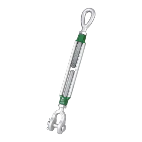
- Se puede usar para elevar y amarrar
- La galvanización asegura durabilidad a largo plazo
- Calidad y soporte fiable de Green Pin®
El Green Pin® EJ Tensor es un tensor con terminales ojo-mordaza, generalmente conforme a ASTM F1145-92. La mordaza tiene montado un perno de seguridad para tamaños con una rosca de diámetro hasta 5/8 inch y tiene montado un pasador de horquilla para tamaños con una rosca de diámetro de 3/4 inch y por encima. Una de las características exclusivas de los Green Pin® Tensor como estos es que pueden utilizarse tanto para elevación como para amarre. La galvanización del Green Pin® EJ Tensor asegura su durabilidad a largo plazo. El tensor está disponible en una gama con una rosca de diámetro de 3/8" (toma de 6") a 2 3/4" (toma de 24".
-
Código de productoG-6315
-
Materialacero de alta resistencia forjado SAE 1035 o 1045
-
Factor de SeguridadCMR = 5 x CMT
-
Acabadogalvanizado en caliente
-
Temperatura-20°C hasta +200°C
-
Certificación
- 2.1
- 2.2
- 3.1
- MTCa
- CE
-
Estándargeneralmente según ASTM F1145-92antes U.S. Fed. Spec. FF-T-791b
| Article code |
carga máxima de trabajo
(ton)
|
carga máxima de trabajo
(ton)
|
capacidad de abertu (Pulgadas)
|
capacidad de abertu (Pulgadas)
|
diámetro rosca (Pulgadas)
A
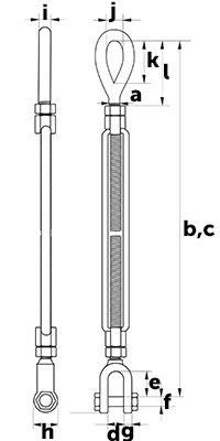
|
diámetro rosca (Pulgadas)
A
|
longitud posicion cerrada
(mm)
B
|
longitud posicion cerrada (P)
B
|
longitud posicion abierta (P)
C
|
longitud posicion abierta
(mm)
C
|
abertura horquilla
(mm)
D
|
abertura horquilla (Pulgadas)
D
|
longitud interior horquilla(P)
E
|
longitud interior horquilla
(mm)
E
|
diámetro bulon horquilla(Pulg)
F
|
diámetro bulon horquilla
(mm)
F
|
espesor ojo horquilla
(mm)
G
|
espesor ojo horquilla (Pulg)
G
|
diámetro ojo horquilla (Pulg)
H
|
diámetro ojo horquilla
(mm)
H
|
diámetro ojo
(mm)
I
|
diámetro ojo (Pulgadas)
I
|
ancho interior ojo
(mm)
J
|
ancho interior ojo (Pulgadas)
J
|
longitud interior ojo (Pulg)
K
|
longitud interior ojo
(mm)
K
|
longitud posicion cerrada (P)
L
|
longitud posicion cerrada
(mm)
L
|
Peso neto (KG) | Peso neto (LBS) | |
|---|---|---|---|---|---|---|---|---|---|---|---|---|---|---|---|---|---|---|---|---|---|---|---|---|---|---|---|---|---|---|---|
| SSGPGO1006 | 0,54 | 6 | 3/8 | 283 | 418 | 12 | 21 | 8 | 9 | 21 | 10 | 13 | 29 | 49 | 0.52 | ||||||||||||||||
| SSGPGO1006 | 0,54 | 6 | 3/8 | 11 5/32 | 16 1/2 | 15/32 | 13/16 | 5/16 | 11/32 | 13/16 | 13/32 | 1/2 | 1 5/32 | 1 15/16 | 1.15 | ||||||||||||||||
| SSGPGO1206 | 1 | 6 | 1/2 | 315 | 446 | 16 | 26 | 10 | 11 | 25 | 12 | 18 | 36 | 58 | 0.88 | ||||||||||||||||
| SSGPGO1206 | 1 | 6 | 1/2 | 12 3/8 | 17 19/32 | 5/8 | 1 1/32 | 13/32 | 7/16 | 1 | 15/32 | 23/32 | 1 7/16 | 2 9/32 | 1.95 | ||||||||||||||||
| SSGPGO1209 | 1 | 9 | 1/2 | 390 | 598 | 16 | 26 | 10 | 11 | 25 | 12 | 18 | 36 | 57 | 1.13 | ||||||||||||||||
| SSGPGO1209 | 1 | 9 | 1/2 | 15 11/32 | 23 9/16 | 5/8 | 1 1/32 | 13/32 | 7/16 | 1 | 15/32 | 23/32 | 1 7/16 | 2 1/4 | 2.49 | ||||||||||||||||
| SSGPGO1212 | 1 | 12 | 1/2 | 466 | 751 | 16 | 26 | 10 | 11 | 25 | 12 | 18 | 36 | 57 | 1.37 | ||||||||||||||||
| SSGPGO1212 | 1 | 12 | 1/2 | 18 11/32 | 29 9/16 | 5/8 | 1 1/32 | 13/32 | 7/16 | 1 | 15/32 | 23/32 | 1 7/16 | 2 1/4 | 3.01 | ||||||||||||||||
| SSGPGO1606 | 1,59 | 6 | 5/8 | 363 | 486 | 18 | 32 | 13 | 14 | 33 | 14 | 21 | 45 | 79 | 1.55 | ||||||||||||||||
| SSGPGO1606 | 1,59 | 6 | 5/8 | 14 9/32 | 19 5/32 | 23/32 | 1 9/32 | 1/2 | 9/16 | 1 5/16 | 9/16 | 13/16 | 1 25/32 | 3 1/8 | 3.42 | ||||||||||||||||
| SSGPGO1609 | 1,59 | 9 | 5/8 | 438 | 639 | 18 | 32 | 13 | 14 | 33 | 14 | 21 | 45 | 78 | 1.61 | ||||||||||||||||
| SSGPGO1609 | 1,59 | 9 | 5/8 | 17 9/32 | 25 5/32 | 23/32 | 1 9/32 | 1/2 | 9/16 | 1 5/16 | 9/16 | 13/16 | 1 25/32 | 3 3/32 | 3.55 | ||||||||||||||||
| SSGPGO1612 | 1,59 | 12 | 5/8 | 514 | 790 | 18 | 32 | 13 | 14 | 33 | 14 | 21 | 45 | 78 | 2.17 | ||||||||||||||||
| SSGPGO1612 | 1,59 | 12 | 5/8 | 20 1/4 | 31 3/32 | 23/32 | 1 9/32 | 1/2 | 9/16 | 1 5/16 | 9/16 | 13/16 | 1 25/32 | 3 3/32 | 4.79 | ||||||||||||||||
| SSGPGO1906 | 2,36 | 6 | 3/4 | 391 | 510 | 24 | 38 | 16 | 16 | 41 | 17 | 26 | 54 | 89 | 2.28 | ||||||||||||||||
| SSGPGO1906 | 2,36 | 6 | 3/4 | 15 3/8 | 20 3/32 | 15/16 | 1 17/32 | 5/8 | 5/8 | 1 5/8 | 11/16 | 1 1/32 | 2 1/8 | 3 17/32 | 5.02 | ||||||||||||||||
| SSGPGO1909 | 2,36 | 9 | 3/4 | 467 | 663 | 24 | 38 | 16 | 16 | 41 | 17 | 26 | 54 | 89 | 2.82 | ||||||||||||||||
| SSGPGO1909 | 2,36 | 9 | 3/4 | 18 3/8 | 26 3/32 | 15/16 | 1 17/32 | 5/8 | 5/8 | 1 5/8 | 11/16 | 1 1/32 | 2 1/8 | 3 17/32 | 6.23 | ||||||||||||||||
| SSGPGO1912 | 2,36 | 12 | 3/4 | 542 | 815 | 24 | 38 | 16 | 16 | 41 | 17 | 26 | 54 | 88 | 3.16 | ||||||||||||||||
| SSGPGO1912 | 2,36 | 12 | 3/4 | 21 11/32 | 32 3/32 | 15/16 | 1 17/32 | 5/8 | 5/8 | 1 5/8 | 11/16 | 1 1/32 | 2 1/8 | 3 1/2 | 6.97 | ||||||||||||||||
| SSGPGO1918 | 2,36 | 18 | 3/4 | 694 | 1120 | 24 | 38 | 16 | 16 | 41 | 17 | 26 | 54 | 89 | 4.10 | ||||||||||||||||
| SSGPGO1918 | 2,36 | 18 | 3/4 | 27 5/16 | 44 3/32 | 15/16 | 1 17/32 | 5/8 | 5/8 | 1 5/8 | 11/16 | 1 1/32 | 2 1/8 | 3 17/32 | 9.05 | ||||||||||||||||
| SSGPGO2212 | 3,27 | 12 | 7/8 | 583 | 848 | 27 | 42 | 19 | 19 | 48 | 20 | 32 | 61 | 101 | 4.10 | ||||||||||||||||
| SSGPGO2212 | 3,27 | 12 | 7/8 | 22 15/16 | 33 3/8 | 1 3/32 | 1 11/16 | 3/4 | 3/4 | 1 29/32 | 25/32 | 1 9/32 | 2 3/8 | 3 31/32 | 9.04 | ||||||||||||||||
| SSGPGO2218 | 3,27 | 18 | 7/8 | 735 | 1153 | 27 | 42 | 19 | 19 | 48 | 20 | 32 | 61 | 101 | 5.84 | ||||||||||||||||
| SSGPGO2218 | 3,27 | 18 | 7/8 | 28 29/32 | 45 13/32 | 1 3/32 | 1 11/16 | 3/4 | 3/4 | 1 29/32 | 25/32 | 1 9/32 | 2 3/8 | 3 31/32 | 12.9 | ||||||||||||||||
| SSGPGO2506 | 4,54 | 6 | 1 | 473 | 579 | 31 | 50 | 22 | 20 | 54 | 24 | 37 | 76 | 118 | 4.60 | ||||||||||||||||
| SSGPGO2506 | 4,54 | 6 | 1 | 18 5/8 | 22 25/32 | 1 1/4 | 1 31/32 | 7/8 | 25/32 | 2 1/8 | 15/16 | 1 1/2 | 3 | 4 5/8 | 10.1 | ||||||||||||||||
| SSGPGO2512 | 4,54 | 12 | 1 | 624 | 884 | 31 | 50 | 22 | 20 | 54 | 24 | 37 | 76 | 117 | 6.17 | ||||||||||||||||
| SSGPGO2512 | 4,54 | 12 | 1 | 24 9/16 | 34 25/32 | 1 1/4 | 1 31/32 | 7/8 | 25/32 | 2 1/8 | 15/16 | 1 1/2 | 3 | 4 19/32 | 13.6 | ||||||||||||||||
| SSGPGO2518 | 4,54 | 18 | 1 | 776 | 1190 | 31 | 50 | 22 | 20 | 54 | 24 | 37 | 76 | 117 | 7.10 | ||||||||||||||||
| SSGPGO2518 | 4,54 | 18 | 1 | 30 17/32 | 46 27/32 | 1 1/4 | 1 31/32 | 7/8 | 25/32 | 2 1/8 | 15/16 | 1 1/2 | 3 | 4 19/32 | 15.7 | ||||||||||||||||
| SSGPGO2524 | 4,5 | 24 | 1 | 928 | 1494 | 31 | 50 | 22 | 20 | 54 | 24 | 37 | 76 | 116 | 8.35 | ||||||||||||||||
| SSGPGO2524 | 4,5 | 24 | 1 | 36 17/32 | 58 13/16 | 1 1/4 | 1 31/32 | 7/8 | 25/32 | 2 1/8 | 15/16 | 1 1/2 | 3 | 4 9/16 | 18.4 | ||||||||||||||||
| SSGPGO3212 | 6,9 | 12 | 1 1/4 | 677 | 950 | 44 | 71 | 29 | 26 | 68 | 29 | 47 | 91 | 145 | 10.4 | ||||||||||||||||
| SSGPGO3212 | 6,9 | 12 | 1 1/4 | 26 5/8 | 37 3/8 | 1 3/4 | 2 25/32 | 1 5/32 | 1 1/32 | 2 11/16 | 1 5/32 | 1 7/8 | 3 19/32 | 5 23/32 | 23.0 | ||||||||||||||||
| SSGPGO3218 | 6,9 | 18 | 1 1/4 | 833 | 1258 | 44 | 71 | 29 | 26 | 68 | 29 | 47 | 91 | 144 | 11.5 | ||||||||||||||||
| SSGPGO3218 | 6,9 | 18 | 1 1/4 | 32 25/32 | 49 17/32 | 1 3/4 | 2 25/32 | 1 5/32 | 1 1/32 | 2 11/16 | 1 5/32 | 1 7/8 | 3 19/32 | 5 11/16 | 25.3 | ||||||||||||||||
| SSGPGO3224 | 6,9 | 24 | 1 1/4 | 989 | 1566 | 44 | 71 | 29 | 26 | 68 | 29 | 47 | 91 | 144 | 13.2 | ||||||||||||||||
| SSGPGO3224 | 6,9 | 24 | 1 1/4 | 38 15/16 | 61 21/32 | 1 3/4 | 2 25/32 | 1 5/32 | 1 1/32 | 2 11/16 | 1 5/32 | 1 7/8 | 3 19/32 | 5 11/16 | 29.2 | ||||||||||||||||
| SSGPGO3812 | 9,71 | 12 | 1 1/2 | 716 | 983 | 52 | 71 | 35 | 28 | 80 | 32 | 55 | 106 | 156 | 13.9 | ||||||||||||||||
| SSGPGO3812 | 9,71 | 12 | 1 1/2 | 28 5/32 | 38 23/32 | 2 1/32 | 2 25/32 | 1 3/8 | 1 1/8 | 3 5/32 | 1 9/32 | 2 5/32 | 4 5/32 | 6 1/8 | 30.5 | ||||||||||||||||
| SSGPGO3818 | 9,71 | 18 | 1 1/2 | 871 | 1290 | 52 | 71 | 35 | 28 | 80 | 32 | 55 | 106 | 160 | 16.7 | ||||||||||||||||
| SSGPGO3818 | 9,71 | 18 | 1 1/2 | 34 9/32 | 50 25/32 | 2 1/32 | 2 25/32 | 1 3/8 | 1 1/8 | 3 5/32 | 1 9/32 | 2 5/32 | 4 5/32 | 6 9/32 | 36.8 | ||||||||||||||||
| SSGPGO3824 | 9,71 | 24 | 1 1/2 | 1023 | 1594 | 52 | 71 | 35 | 28 | 80 | 32 | 55 | 106 | 158 | 19.7 | ||||||||||||||||
| SSGPGO3824 | 9,71 | 24 | 1 1/2 | 40 9/32 | 60 3/4 | 2 1/32 | 2 25/32 | 1 3/8 | 1 1/8 | 3 5/32 | 1 9/32 | 2 5/32 | 4 5/32 | 6 3/16 | 43.4 | ||||||||||||||||
| SSGPGO4518 | 12,7 | 18 | 1 3/4 | 979 | 1356 | 60 | 86 | 41 | 33 | 90 | 38 | 61 | 120 | 197 | 25.1 | ||||||||||||||||
| SSGPGO4518 | 12,7 | 18 | 1 3/4 | 38 9/16 | 53 13/32 | 2 11/32 | 3 3/8 | 1 5/8 | 1 5/16 | 3 9/16 | 1 17/32 | 2 3/8 | 4 23/32 | 7 3/4 | 55.3 | ||||||||||||||||
| SSGPGO4524 | 12,7 | 24 | 1 3/4 | 1130 | 1662 | 60 | 86 | 41 | 33 | 90 | 38 | 61 | 120 | 196 | 29 | ||||||||||||||||
| SSGPGO4524 | 12,7 | 24 | 1 3/4 | 44 1/2 | 65 7/16 | 2 11/32 | 3 3/8 | 1 5/8 | 1 5/16 | 3 9/16 | 1 17/32 | 2 3/8 | 4 23/32 | 7 23/32 | 64.0 | ||||||||||||||||
| SSGPGO5024 | 16,8 | 24 | 2 | 1208 | 1728 | 63 | 93 | 51 | 40 | 107 | 46 | 69 | 147 | 230 | 42 | ||||||||||||||||
| SSGPGO5024 | 16,8 | 24 | 2 | 47 9/16 | 68 1/32 | 2 1/2 | 3 11/16 | 2 | 1 19/32 | 4 3/16 | 1 13/16 | 2 23/32 | 5 25/32 | 9 3/32 | 92.6 | ||||||||||||||||
| SSGPGO6424 | 27,2 | 24 | 2 1/2 | 1343 | 1899 | 75 | 114 | 57 | 41 | 143 | 51 | 80 | 165 | 274 | 68.5 | ||||||||||||||||
| SSGPGO6424 | 27,2 | 24 | 2 1/2 | 52 7/8 | 74 25/32 | 2 15/16 | 4 1/2 | 2 1/4 | 1 5/8 | 5 5/8 | 2 | 3 5/32 | 6 1/2 | 10 25/32 | 151 | ||||||||||||||||
| SSGPGO6924 | 34 | 24 | 2 3/4 | 1399 | 1953 | 90 | 110 | 70 | 41 | 158 | 57 | 84 | 178 | 284 | 93 | ||||||||||||||||
| SSGPGO6924 | 34 | 24 | 2 3/4 | 55 3/32 | 76 29/32 | 3 9/16 | 4 5/16 | 2 3/4 | 1 5/8 | 6 3/16 | 2 1/4 | 3 5/16 | 7 | 11 3/16 | 205 |
Do you have questions about this product? Don't hesitate to contact us.
Preguntas frecuentes relacionadas
Si va a las páginas de producto de productos individuales en este sitio web, puede descargar el dibujo CAD de ese producto:
- En la página del producto, ve a la tabla con dimensiones
- Seleccione el tamaño del producto que le interesa
- Aparecerá un botón Descargar
Si no aparece el botón Descargar, no hay disponible ningún dibujo CAD para este producto.
Tensores Green Pin® G-6311, G-6312, G-6313, G-6314, G-6315, G-6323 y G-6333 son adecuados para aplicaciones elevadoras. Estos artículos poseen una carga de prueba equivalente a 2x CMT y una carga mínima de rotura equivalente a 5x CMT. Las «Instrucciones de uso» publicadas en nuestro catálogo deben respetarse en todo momento.
Nota: No se permite ajustar la longitud del tensor bajo carga completa. Se permite la tensión por debajo de la CMT. Se recomienda ajustar en primer lugar la longitud del tensor y, a continuación, cargar los tensores a una tensión determinada. La tensión no podrá exceder la capacidad completa (CMT).
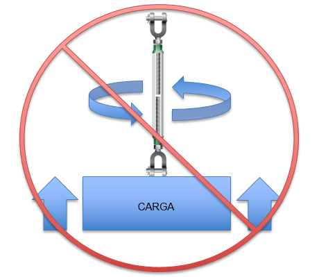
Nota: No se permite elevar una carga tensando (rotando el cuerpo) el tensor, tal y como se muestra en la imagen siguiente:
FAQ-Reference PI-02-01. Revision B.
¡No! Los productos Green Pin® se han tratado con un buen tratamiento térmico que se traduce en una carga de rotura mínima y otras propiedades mecánicas específicas. Estas propiedades se destruirán por el calor de la soldadura. También puede provocar grietas iniciales y puntos duros que reducirán drásticamente la resistencia a la flexión y global.
A excepción de los productos Green Pin® GH y PAS, los cuales deben soldarse a una superficie para su correcto funcionamiento. Para estos elementos, siga las instrucciones disponibles en Van Beest B.V.
BN = Tornillo de seguridad
CL = Conexión directa
CP = Pasador de retención
D = Asa en D
E = Conexión tipo oja
EE = Ojo-Ojo
EJ = Ojo-Gancho
EH = Ojo-Horquilla
F = Asa en F
FN = Tuerca de bloqueo
FP = Pasador con cabeza embutida
GR10 = Grado 10
GR5 = Grado 5
GR8 = Grado 8
HH = Gancho-Gancho
HK = Gancho
JJ = Horquilla-Horquilla
ROV = Vehículo de Control Remoto
S = Grillete
S/S = Inoxidable
SC= Anillo con rosca
SCL = Conexion directa y giratorio
SE = Conexión giratorio y tipo oja
SQ = Pasador roscado con cabeza cuadrada
Tipo H = Horizontal
Tipo U = Universal (horizontal y vertical)
Tipo V = Vertical
Green Pin® turnbuckles are highly regarded in various industries for their reliability and adaptability, offering a range of specifications tailored to different operational needs. These turnbuckles come in multiple grades, reflecting their strength and load capacity, which are essential for applications ranging from maritime to construction. To discover all Green Pin® turnbuckles, visit the turnbuckles category page here.
Tensor con terminaciones horquilla y ojal y pasador de chaveta o pasador de seguridad (según tamaño), generalmente según ASTM F1145-92
Beneficios
 Se puede usar para elevar y amarrar
- La galvanización asegura durabilidad a largo plazo
- Calidad y soporte fiable de Green Pin®
Descripción
El Green Pin® EJ Tensor es un tensor con terminales ojo-mordaza, generalmente conforme a ASTM F1145-92. La mordaza tiene montado un perno de seguridad para tamaños con una rosca de diámetro hasta 5/8 inch y tiene montado un pasador de horquilla para tamaños con una rosca de diámetro de 3/4 inch y por encima. Una de las características exclusivas de los Green Pin® Tensor como estos es que pueden utilizarse tanto para elevación como para amarre. La galvanización del Green Pin® EJ Tensor asegura su durabilidad a largo plazo. El tensor está disponible en una gama con una rosca de diámetro de 3/8" (toma de 6") a 2 3/4" (toma de 24".
Detalles del producto
- Código de productoG-6315
- Materialacero de alta resistencia forjado SAE 1035 o 1045
- Factor de SeguridadCMR = 5 x CMT
- Acabadogalvanizado en caliente
- Temperatura-20°C hasta +200°C
- Certificación 2.1 2.2 3.1 MTCa CE
- Estándargeneralmente según ASTM F1145-92antes U.S. Fed. Spec. FF-T-791b
| Article code | carga máxima de trabajo | capacidad de abertu (Pulgadas) |
|
|
|
|
|
|
|
|
|
|
|
|
Peso neto
(kg) |
|---|---|---|---|---|---|---|---|---|---|---|---|---|---|---|---|
| SSGPGO1006 | 0,54 | 6 | 3/8 | 283 | 418 | 12 | 21 | 8 | 9 | 21 | 10 | 13 | 29 | 49 | 0.52 |
| SSGPGO1206 | 1 | 6 | 1/2 | 315 | 446 | 16 | 26 | 10 | 11 | 25 | 12 | 18 | 36 | 58 | 0.88 |
| SSGPGO1209 | 1 | 9 | 1/2 | 390 | 598 | 16 | 26 | 10 | 11 | 25 | 12 | 18 | 36 | 57 | 1.13 |
| SSGPGO1212 | 1 | 12 | 1/2 | 466 | 751 | 16 | 26 | 10 | 11 | 25 | 12 | 18 | 36 | 57 | 1.37 |
| SSGPGO1606 | 1,59 | 6 | 5/8 | 363 | 486 | 18 | 32 | 13 | 14 | 33 | 14 | 21 | 45 | 79 | 1.55 |
| SSGPGO1609 | 1,59 | 9 | 5/8 | 438 | 639 | 18 | 32 | 13 | 14 | 33 | 14 | 21 | 45 | 78 | 1.61 |
| SSGPGO1612 | 1,59 | 12 | 5/8 | 514 | 790 | 18 | 32 | 13 | 14 | 33 | 14 | 21 | 45 | 78 | 2.17 |
| SSGPGO1906 | 2,36 | 6 | 3/4 | 391 | 510 | 24 | 38 | 16 | 16 | 41 | 17 | 26 | 54 | 89 | 2.28 |
| SSGPGO1909 | 2,36 | 9 | 3/4 | 467 | 663 | 24 | 38 | 16 | 16 | 41 | 17 | 26 | 54 | 89 | 2.82 |
| SSGPGO1912 | 2,36 | 12 | 3/4 | 542 | 815 | 24 | 38 | 16 | 16 | 41 | 17 | 26 | 54 | 88 | 3.16 |
| SSGPGO1918 | 2,36 | 18 | 3/4 | 694 | 1120 | 24 | 38 | 16 | 16 | 41 | 17 | 26 | 54 | 89 | 4.10 |
| SSGPGO2212 | 3,27 | 12 | 7/8 | 583 | 848 | 27 | 42 | 19 | 19 | 48 | 20 | 32 | 61 | 101 | 4.10 |
| Article code | carga máxima de trabajo | capacidad de abertu (Pulgadas) |
|
|
|
|
|
|
|
|
|
|
|
|
Peso neto
(kg) |
|---|---|---|---|---|---|---|---|---|---|---|---|---|---|---|---|
| SSGPGO2218 | 3,27 | 18 | 7/8 | 735 | 1153 | 27 | 42 | 19 | 19 | 48 | 20 | 32 | 61 | 101 | 5.84 |
| SSGPGO2506 | 4,54 | 6 | 1 | 473 | 579 | 31 | 50 | 22 | 20 | 54 | 24 | 37 | 76 | 118 | 4.60 |
| SSGPGO2512 | 4,54 | 12 | 1 | 624 | 884 | 31 | 50 | 22 | 20 | 54 | 24 | 37 | 76 | 117 | 6.17 |
| SSGPGO2518 | 4,54 | 18 | 1 | 776 | 1190 | 31 | 50 | 22 | 20 | 54 | 24 | 37 | 76 | 117 | 7.10 |
| SSGPGO2524 | 4,5 | 24 | 1 | 928 | 1494 | 31 | 50 | 22 | 20 | 54 | 24 | 37 | 76 | 116 | 8.35 |
| SSGPGO3212 | 6,9 | 12 | 1 1/4 | 677 | 950 | 44 | 71 | 29 | 26 | 68 | 29 | 47 | 91 | 145 | 10.4 |
| SSGPGO3218 | 6,9 | 18 | 1 1/4 | 833 | 1258 | 44 | 71 | 29 | 26 | 68 | 29 | 47 | 91 | 144 | 11.5 |
| SSGPGO3224 | 6,9 | 24 | 1 1/4 | 989 | 1566 | 44 | 71 | 29 | 26 | 68 | 29 | 47 | 91 | 144 | 13.2 |
| SSGPGO3812 | 9,71 | 12 | 1 1/2 | 716 | 983 | 52 | 71 | 35 | 28 | 80 | 32 | 55 | 106 | 156 | 13.9 |
| SSGPGO3818 | 9,71 | 18 | 1 1/2 | 871 | 1290 | 52 | 71 | 35 | 28 | 80 | 32 | 55 | 106 | 160 | 16.7 |
| SSGPGO3824 | 9,71 | 24 | 1 1/2 | 1023 | 1594 | 52 | 71 | 35 | 28 | 80 | 32 | 55 | 106 | 158 | 19.7 |
| SSGPGO4518 | 12,7 | 18 | 1 3/4 | 979 | 1356 | 60 | 86 | 41 | 33 | 90 | 38 | 61 | 120 | 197 | 25.1 |
| SSGPGO4524 | 12,7 | 24 | 1 3/4 | 1130 | 1662 | 60 | 86 | 41 | 33 | 90 | 38 | 61 | 120 | 196 | 29 |
| SSGPGO5024 | 16,8 | 24 | 2 | 1208 | 1728 | 63 | 93 | 51 | 40 | 107 | 46 | 69 | 147 | 230 | 42 |
| SSGPGO6424 | 27,2 | 24 | 2 1/2 | 1343 | 1899 | 75 | 114 | 57 | 41 | 143 | 51 | 80 | 165 | 274 | 68.5 |
| SSGPGO6924 | 34 | 24 | 2 3/4 | 1399 | 1953 | 90 | 110 | 70 | 41 | 158 | 57 | 84 | 178 | 284 | 93 |
| Article code | carga máxima de trabajo | capacidad de abertu (Pulgadas) |
|
|
|
|
|
|
|
|
|
|
|
|
Peso neto
(kg) |
|---|---|---|---|---|---|---|---|---|---|---|---|---|---|---|---|
| SSGPGO4524 | 12,7 | 24 | 1 3/4 | 1130 | 1662 | 60 | 86 | 41 | 33 | 90 | 38 | 61 | 120 | 196 | 29 |
| SSGPGO5024 | 16,8 | 24 | 2 | 1208 | 1728 | 63 | 93 | 51 | 40 | 107 | 46 | 69 | 147 | 230 | 42 |
| SSGPGO6424 | 27,2 | 24 | 2 1/2 | 1343 | 1899 | 75 | 114 | 57 | 41 | 143 | 51 | 80 | 165 | 274 | 68.5 |
| SSGPGO6924 | 34 | 24 | 2 3/4 | 1399 | 1953 | 90 | 110 | 70 | 41 | 158 | 57 | 84 | 178 | 284 | 93 |
| Article code | carga máxima de trabajo | capacidad de abertu (Pulgadas) |
|
|
|
|
|
|
|
|
|
|
|
|
Peso neto
(LBS) |
|---|---|---|---|---|---|---|---|---|---|---|---|---|---|---|---|
| SSGPGO1006 | 0,54 | 6 | 3/8 | 11 5/32 | 16 1/2 | 15/32 | 13/16 | 5/16 | 11/32 | 13/16 | 13/32 | 1/2 | 1 5/32 | 1 15/16 | 1.15 |
| SSGPGO1206 | 1 | 6 | 1/2 | 12 3/8 | 17 19/32 | 5/8 | 1 1/32 | 13/32 | 7/16 | 1 | 15/32 | 23/32 | 1 7/16 | 2 9/32 | 1.95 |
| SSGPGO1209 | 1 | 9 | 1/2 | 15 11/32 | 23 9/16 | 5/8 | 1 1/32 | 13/32 | 7/16 | 1 | 15/32 | 23/32 | 1 7/16 | 2 1/4 | 2.49 |
| SSGPGO1212 | 1 | 12 | 1/2 | 18 11/32 | 29 9/16 | 5/8 | 1 1/32 | 13/32 | 7/16 | 1 | 15/32 | 23/32 | 1 7/16 | 2 1/4 | 3.01 |
| SSGPGO1606 | 1,59 | 6 | 5/8 | 14 9/32 | 19 5/32 | 23/32 | 1 9/32 | 1/2 | 9/16 | 1 5/16 | 9/16 | 13/16 | 1 25/32 | 3 1/8 | 3.42 |
| SSGPGO1609 | 1,59 | 9 | 5/8 | 17 9/32 | 25 5/32 | 23/32 | 1 9/32 | 1/2 | 9/16 | 1 5/16 | 9/16 | 13/16 | 1 25/32 | 3 3/32 | 3.55 |
| SSGPGO1612 | 1,59 | 12 | 5/8 | 20 1/4 | 31 3/32 | 23/32 | 1 9/32 | 1/2 | 9/16 | 1 5/16 | 9/16 | 13/16 | 1 25/32 | 3 3/32 | 4.79 |
| SSGPGO1906 | 2,36 | 6 | 3/4 | 15 3/8 | 20 3/32 | 15/16 | 1 17/32 | 5/8 | 5/8 | 1 5/8 | 11/16 | 1 1/32 | 2 1/8 | 3 17/32 | 5.02 |
| SSGPGO1909 | 2,36 | 9 | 3/4 | 18 3/8 | 26 3/32 | 15/16 | 1 17/32 | 5/8 | 5/8 | 1 5/8 | 11/16 | 1 1/32 | 2 1/8 | 3 17/32 | 6.23 |
| SSGPGO1912 | 2,36 | 12 | 3/4 | 21 11/32 | 32 3/32 | 15/16 | 1 17/32 | 5/8 | 5/8 | 1 5/8 | 11/16 | 1 1/32 | 2 1/8 | 3 1/2 | 6.97 |
| SSGPGO1918 | 2,36 | 18 | 3/4 | 27 5/16 | 44 3/32 | 15/16 | 1 17/32 | 5/8 | 5/8 | 1 5/8 | 11/16 | 1 1/32 | 2 1/8 | 3 17/32 | 9.05 |
| SSGPGO2212 | 3,27 | 12 | 7/8 | 22 15/16 | 33 3/8 | 1 3/32 | 1 11/16 | 3/4 | 3/4 | 1 29/32 | 25/32 | 1 9/32 | 2 3/8 | 3 31/32 | 9.04 |
| Article code | carga máxima de trabajo | capacidad de abertu (Pulgadas) |
|
|
|
|
|
|
|
|
|
|
|
|
Peso neto
(LBS) |
|---|---|---|---|---|---|---|---|---|---|---|---|---|---|---|---|
| SSGPGO2218 | 3,27 | 18 | 7/8 | 28 29/32 | 45 13/32 | 1 3/32 | 1 11/16 | 3/4 | 3/4 | 1 29/32 | 25/32 | 1 9/32 | 2 3/8 | 3 31/32 | 12.9 |
| SSGPGO2506 | 4,54 | 6 | 1 | 18 5/8 | 22 25/32 | 1 1/4 | 1 31/32 | 7/8 | 25/32 | 2 1/8 | 15/16 | 1 1/2 | 3 | 4 5/8 | 10.1 |
| SSGPGO2512 | 4,54 | 12 | 1 | 24 9/16 | 34 25/32 | 1 1/4 | 1 31/32 | 7/8 | 25/32 | 2 1/8 | 15/16 | 1 1/2 | 3 | 4 19/32 | 13.6 |
| SSGPGO2518 | 4,54 | 18 | 1 | 30 17/32 | 46 27/32 | 1 1/4 | 1 31/32 | 7/8 | 25/32 | 2 1/8 | 15/16 | 1 1/2 | 3 | 4 19/32 | 15.7 |
| SSGPGO2524 | 4,5 | 24 | 1 | 36 17/32 | 58 13/16 | 1 1/4 | 1 31/32 | 7/8 | 25/32 | 2 1/8 | 15/16 | 1 1/2 | 3 | 4 9/16 | 18.4 |
| SSGPGO3212 | 6,9 | 12 | 1 1/4 | 26 5/8 | 37 3/8 | 1 3/4 | 2 25/32 | 1 5/32 | 1 1/32 | 2 11/16 | 1 5/32 | 1 7/8 | 3 19/32 | 5 23/32 | 23.0 |
| SSGPGO3218 | 6,9 | 18 | 1 1/4 | 32 25/32 | 49 17/32 | 1 3/4 | 2 25/32 | 1 5/32 | 1 1/32 | 2 11/16 | 1 5/32 | 1 7/8 | 3 19/32 | 5 11/16 | 25.3 |
| SSGPGO3224 | 6,9 | 24 | 1 1/4 | 38 15/16 | 61 21/32 | 1 3/4 | 2 25/32 | 1 5/32 | 1 1/32 | 2 11/16 | 1 5/32 | 1 7/8 | 3 19/32 | 5 11/16 | 29.2 |
| SSGPGO3812 | 9,71 | 12 | 1 1/2 | 28 5/32 | 38 23/32 | 2 1/32 | 2 25/32 | 1 3/8 | 1 1/8 | 3 5/32 | 1 9/32 | 2 5/32 | 4 5/32 | 6 1/8 | 30.5 |
| SSGPGO3818 | 9,71 | 18 | 1 1/2 | 34 9/32 | 50 25/32 | 2 1/32 | 2 25/32 | 1 3/8 | 1 1/8 | 3 5/32 | 1 9/32 | 2 5/32 | 4 5/32 | 6 9/32 | 36.8 |
| SSGPGO3824 | 9,71 | 24 | 1 1/2 | 40 9/32 | 60 3/4 | 2 1/32 | 2 25/32 | 1 3/8 | 1 1/8 | 3 5/32 | 1 9/32 | 2 5/32 | 4 5/32 | 6 3/16 | 43.4 |
| SSGPGO4518 | 12,7 | 18 | 1 3/4 | 38 9/16 | 53 13/32 | 2 11/32 | 3 3/8 | 1 5/8 | 1 5/16 | 3 9/16 | 1 17/32 | 2 3/8 | 4 23/32 | 7 3/4 | 55.3 |
| SSGPGO4524 | 12,7 | 24 | 1 3/4 | 44 1/2 | 65 7/16 | 2 11/32 | 3 3/8 | 1 5/8 | 1 5/16 | 3 9/16 | 1 17/32 | 2 3/8 | 4 23/32 | 7 23/32 | 64.0 |
| SSGPGO5024 | 16,8 | 24 | 2 | 47 9/16 | 68 1/32 | 2 1/2 | 3 11/16 | 2 | 1 19/32 | 4 3/16 | 1 13/16 | 2 23/32 | 5 25/32 | 9 3/32 | 92.6 |
| SSGPGO6424 | 27,2 | 24 | 2 1/2 | 52 7/8 | 74 25/32 | 2 15/16 | 4 1/2 | 2 1/4 | 1 5/8 | 5 5/8 | 2 | 3 5/32 | 6 1/2 | 10 25/32 | 151 |
| SSGPGO6924 | 34 | 24 | 2 3/4 | 55 3/32 | 76 29/32 | 3 9/16 | 4 5/16 | 2 3/4 | 1 5/8 | 6 3/16 | 2 1/4 | 3 5/16 | 7 | 11 3/16 | 205 |
| Article code | carga máxima de trabajo | capacidad de abertu (Pulgadas) |
|
|
|
|
|
|
|
|
|
|
|
|
Peso neto
(LBS) |
|---|---|---|---|---|---|---|---|---|---|---|---|---|---|---|---|
| SSGPGO4524 | 12,7 | 24 | 1 3/4 | 44 1/2 | 65 7/16 | 2 11/32 | 3 3/8 | 1 5/8 | 1 5/16 | 3 9/16 | 1 17/32 | 2 3/8 | 4 23/32 | 7 23/32 | 64.0 |
| SSGPGO5024 | 16,8 | 24 | 2 | 47 9/16 | 68 1/32 | 2 1/2 | 3 11/16 | 2 | 1 19/32 | 4 3/16 | 1 13/16 | 2 23/32 | 5 25/32 | 9 3/32 | 92.6 |
| SSGPGO6424 | 27,2 | 24 | 2 1/2 | 52 7/8 | 74 25/32 | 2 15/16 | 4 1/2 | 2 1/4 | 1 5/8 | 5 5/8 | 2 | 3 5/32 | 6 1/2 | 10 25/32 | 151 |
| SSGPGO6924 | 34 | 24 | 2 3/4 | 55 3/32 | 76 29/32 | 3 9/16 | 4 5/16 | 2 3/4 | 1 5/8 | 6 3/16 | 2 1/4 | 3 5/16 | 7 | 11 3/16 | 205 |